In the last part we looked at the flood fill node and how it works. In this part, we will see how this applies to the alignment node and start discussing the details.
The goal is to find some points which can be used to form an alignment matrix. So, the idea I had was to more or less do the same thing as the flood fill. Step around the edges, asking if this reference pixel is a 'corner' or not. Ideally, we would end up with an output that looks something like this.

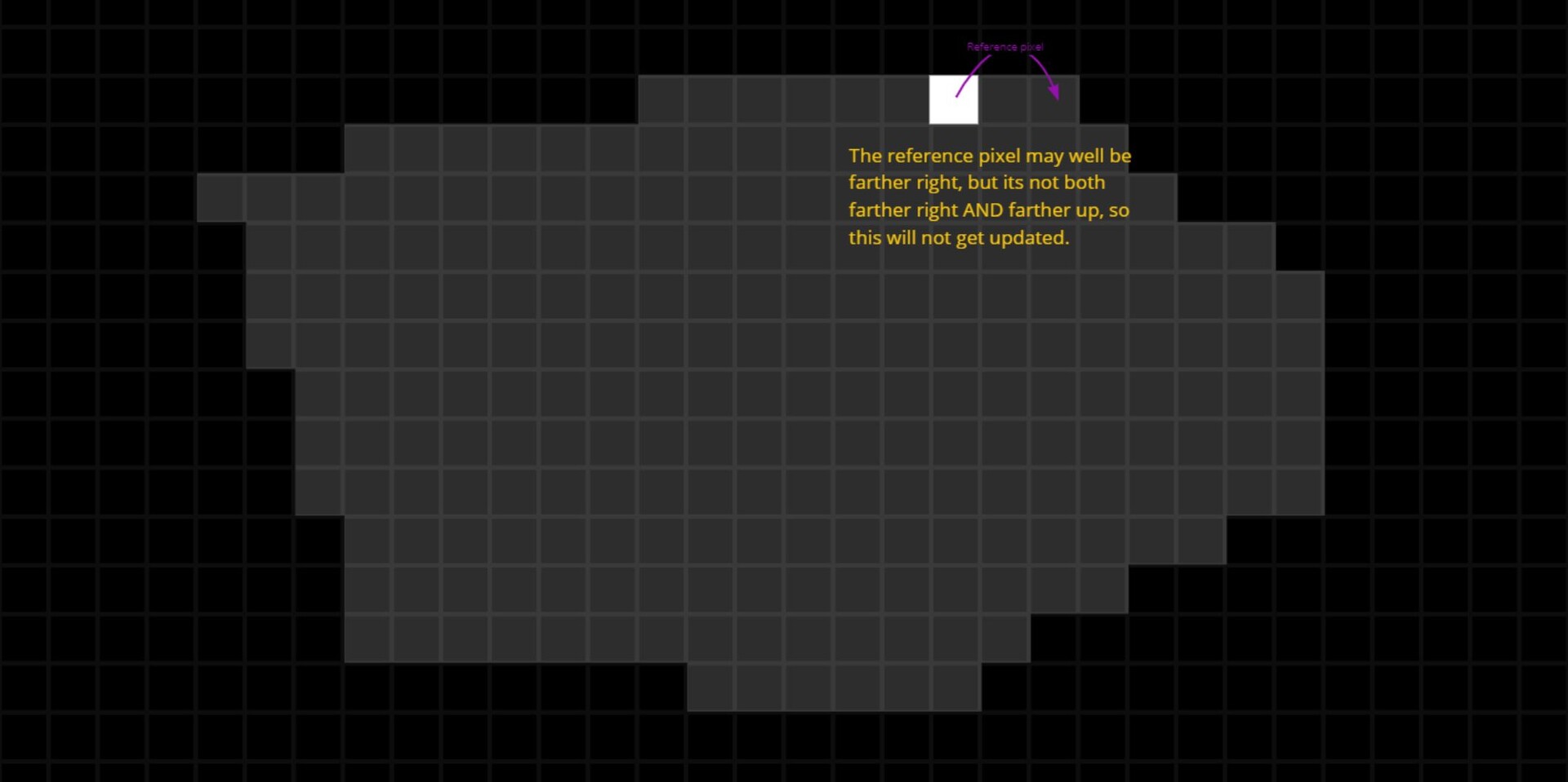
The first idea I had was to use an if statement very similar to the one in the flood fill, where it finds a reference pixel; Is the pixel farther up and right? Is the pixel farther down and left? and so on...
However, this turned out to not work well. Sometimes the node would never converge to a single pixel. I think this is because my if statement was setup with an AND condition: If farther AND farther right. Take this pixel for example, it would fail because while its reference pixel might well be farther to the right, its not farther right and farther up. Essentially I was finding local minimums and never converging fully.
You might think that you could stagger the if statement instead. Something like: If farther right, then check if its farther up. The issue here however is you end up biasing the result to a particular axis.
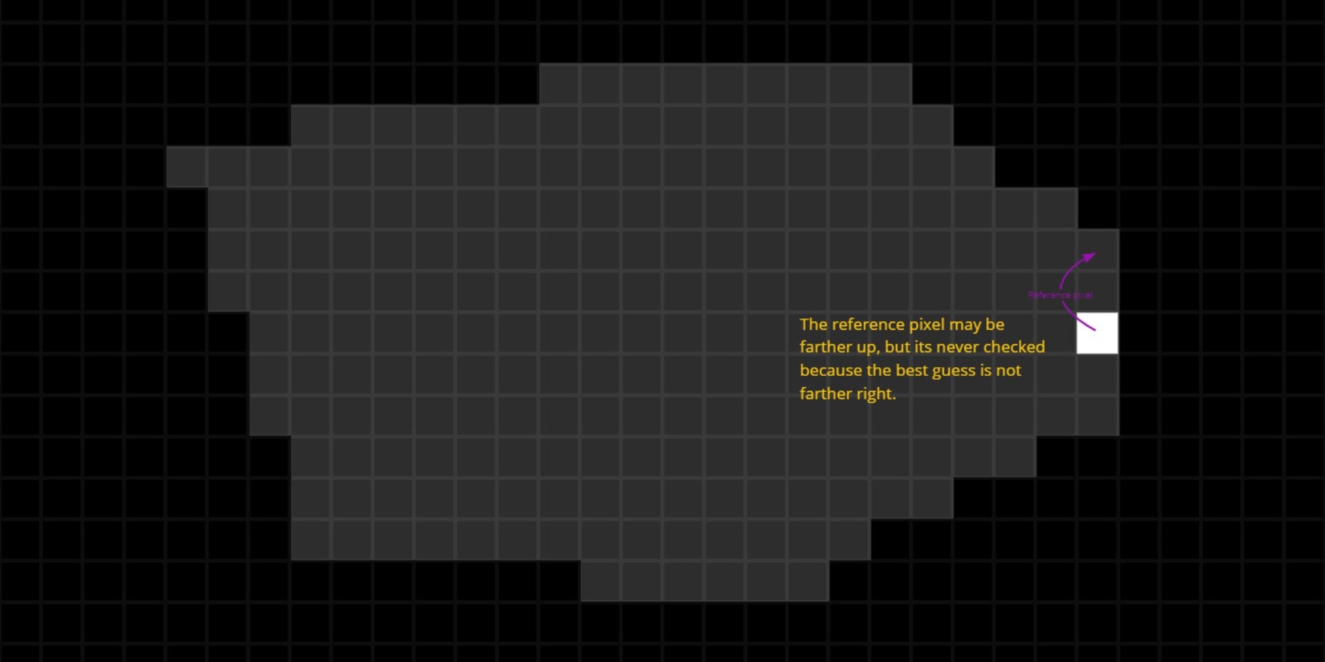
I tried a variety of these condition and never found one that worked. In the case of flood fill, I think it works because its only interested in finding one pixel and it doesn't matter where exactly. So they are able to construct an if statement which is defined fully. In this case though, we need a particular corner, in a particular direction, and that is harder to define.
So instead I decided to use the distance from the center as a way of weighting the question. The idea is this: Always pick the pixel which is farther away from the center, but only if it is pointing in a particular direction.

Now, before we discuss how that is implemented, there is an interesting question. What is the center of the shape? The centroid may be the obvious one, but we don't immediately have that information. And in fact, to calculate that we would need to use a concept called image moments. We will talk more about this at the end of the series.

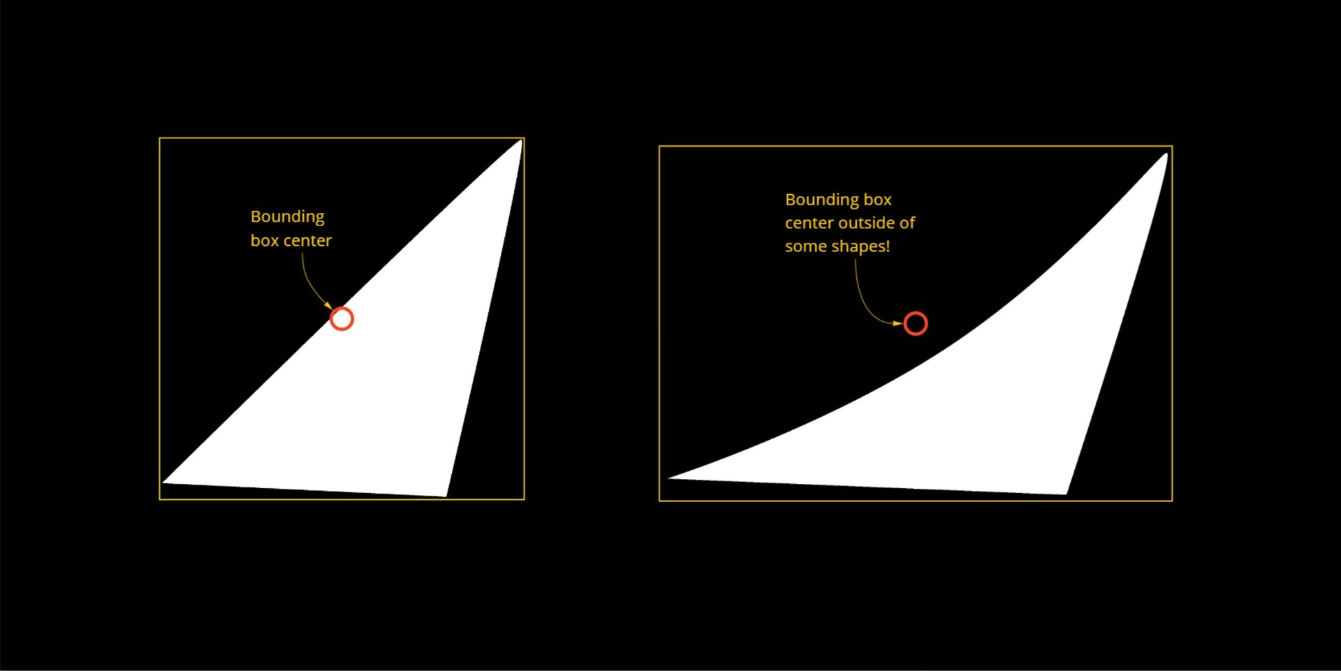
The next logical one might be the center of the bounding box. We do in fact have that information to hand already, it comes with the flood fill node. However, both of these come with other problems; its possible the center actually lays outside of the shape.
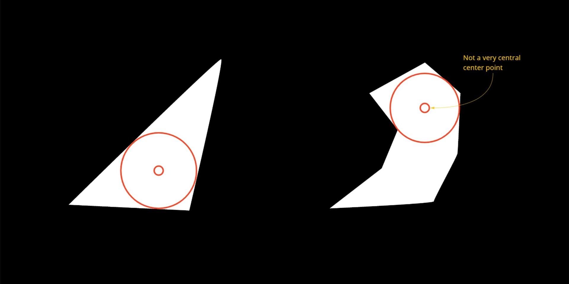
Another approach may be to take the center of a best fit circle. This is something I covered in my last blog series https://www.artstation.com/blogs/benwilson/2WpV/flood-fill-to-corners-development-part-3
The issue here is that its quite a bit more expensive to compute and may not be very 'center' in some shapes.
In the end, I decided to use the bounding box center for simplicity. I wanted to get the node up and running quickly to see if it would even work anyway. After all, my use case was a typical convex shape anyway.
So lets look at how to calculate the distance from the center. There are 3 steps I took for this:
1. The first is to dilate the flood fill to position output, which if you didn't know, gives you the uv position of the bounding box center for each shape.
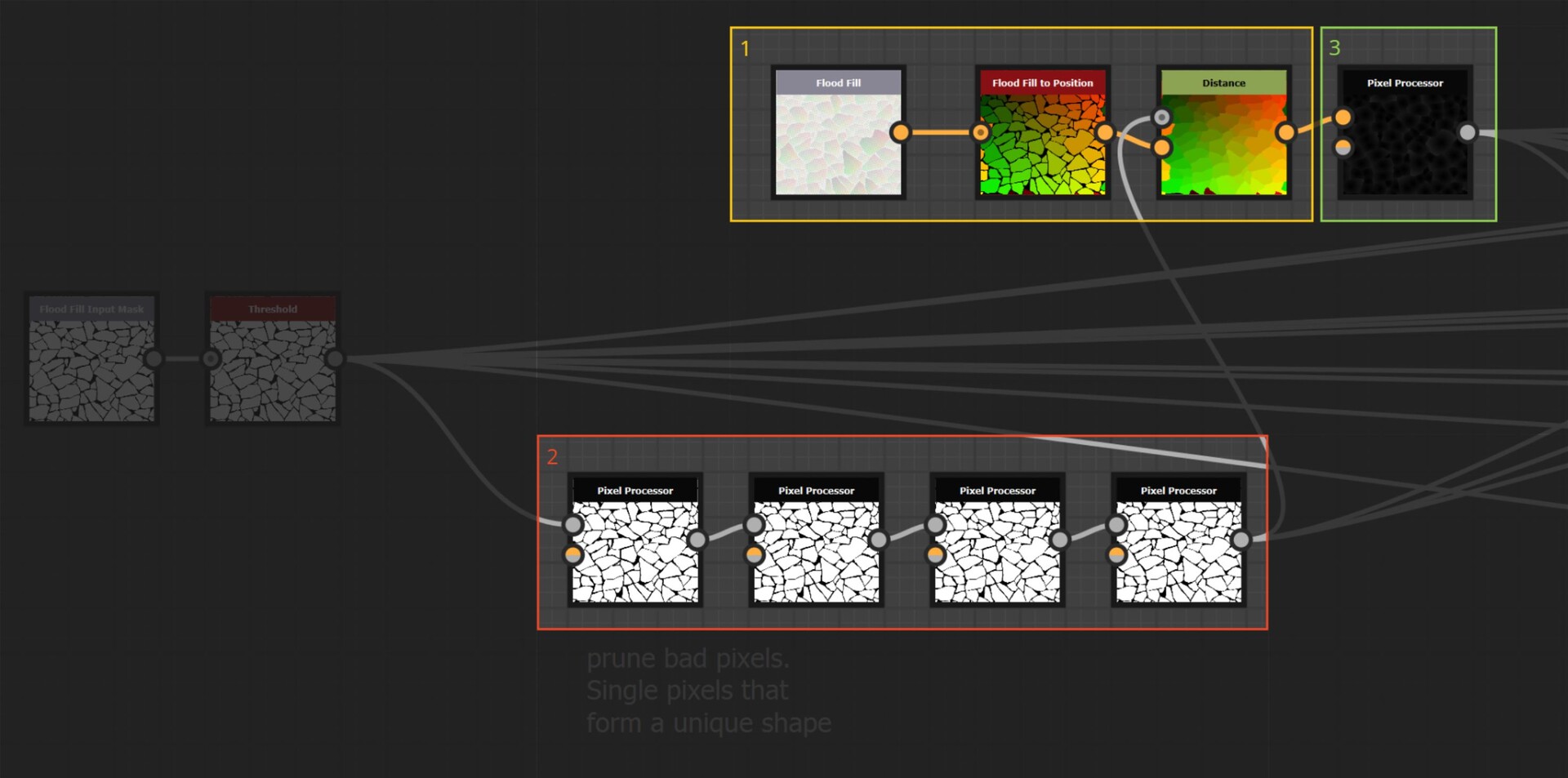
2. The second is a pre pass to try and prune floating pixels which were causing issues in the step functions. Here you can see how the pre pass identify and remove floating pixels.
This is done by looking at each neighbour pixel, counting them up and outputting black if the pixel is isolated. So if a pixel is surrounded by black, except for one pixel, then I assume it to be associated with a shape, but isolated.

There are 4 passes to this, because pruning one pixel might produce another isolated one (in the case of a line), reasoning that four will probably be enough. This is quite hacky, but I want to emphasis again that I am not worrying about making the node fail safe and robust at this point. I needed to prove the theory would work first, which as it turns out, didn't =)
3. This last part is very simple, take the distance between the center point and the center pixel. The farther we are from the center, the larger the distance value will be.

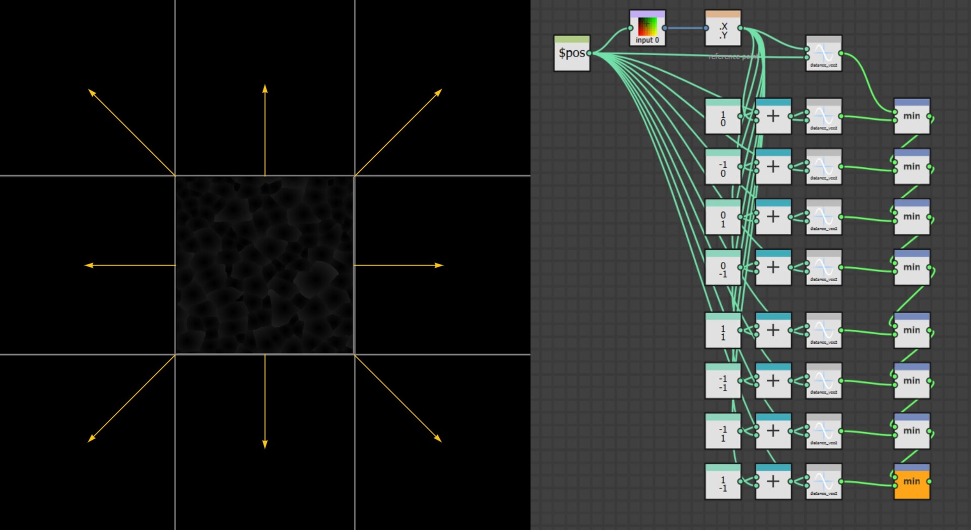
However, this introduces an interesting error when applied to the full tiling texture. When we are close to the border, the center point might actually be on the other end of the texture, leading to artificially large distance values.

To solve this, we must offset the texture by one full tile and then compute the distance, taking which ever is the smallest. Do this for all 8 directions and it will fix the tiling.
This wraps up part 2, in part 3 https://www.artstation.com/blogs/benwilson/opoN/alignment-node-development-part-3 we will continue directly from here and discuss how to use this newly computed distance map. See you soon.