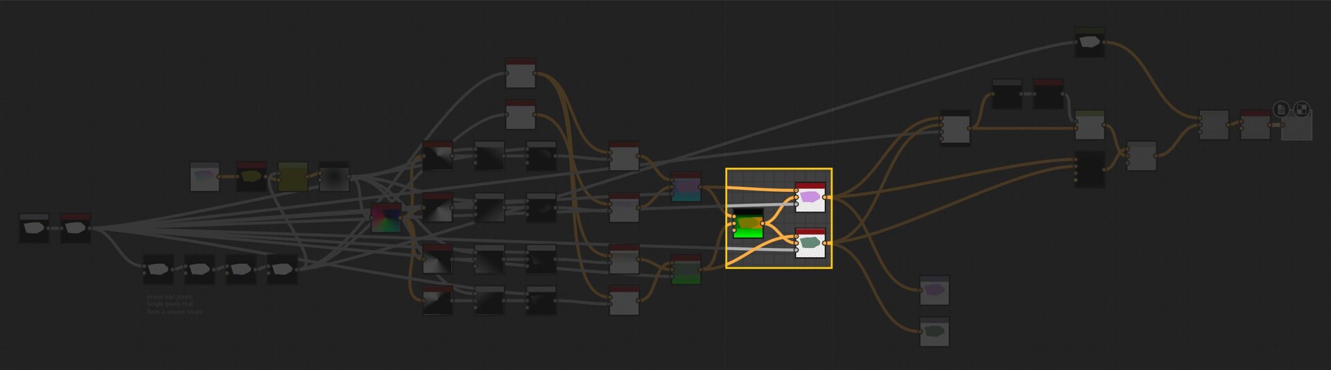
In the last part we just finished off creating our step function and now we will be implementing the rest of the node. The output of the step functions are images with pointers to the farthest pixel in a given direction.
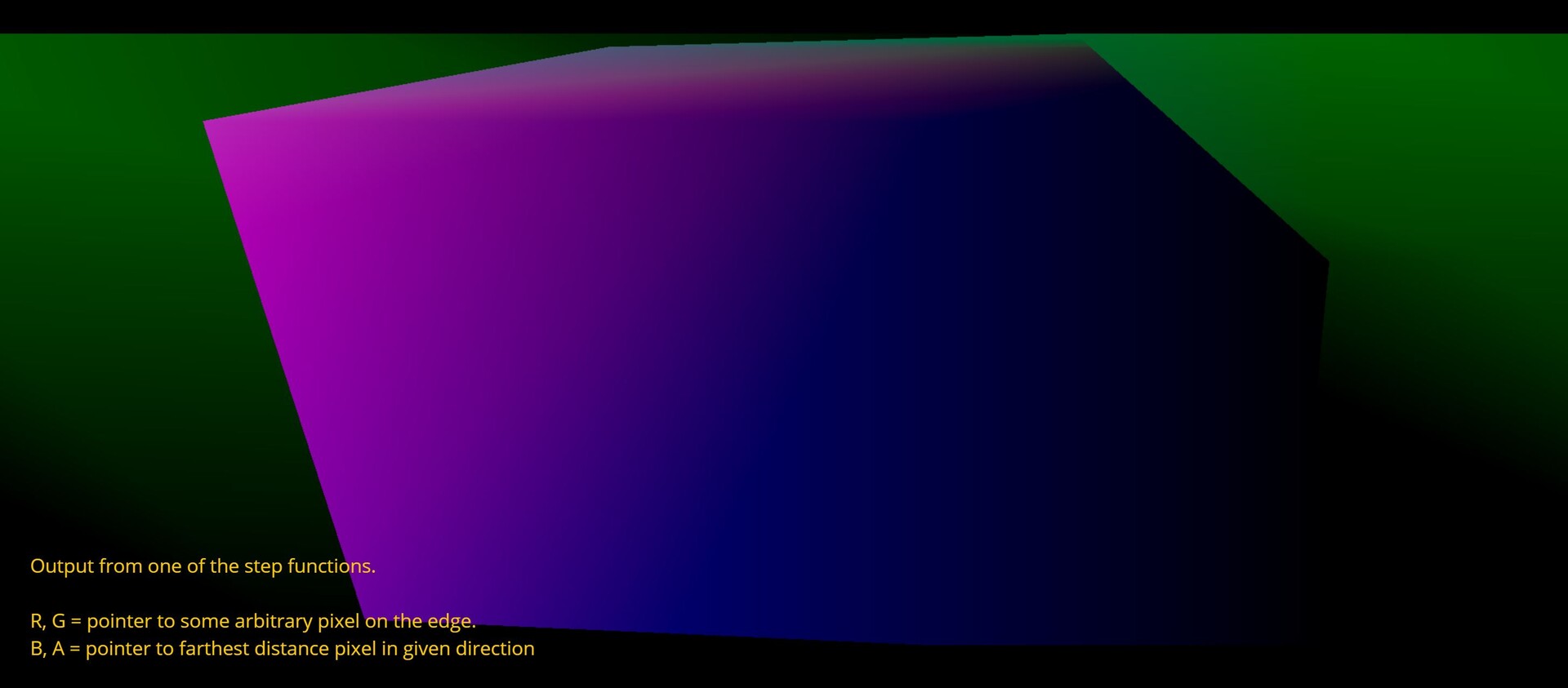
This is in fact everything we need to calculate alignment points. For every pixel, we can now find relevant corner points and form a transformation matrix from it.
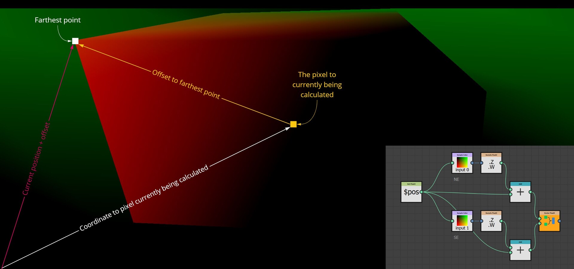
The first step however was to convert this information into uv positions, much the same as the flood fill to position node. This is done by adding the current pixel position to the pointer vector.
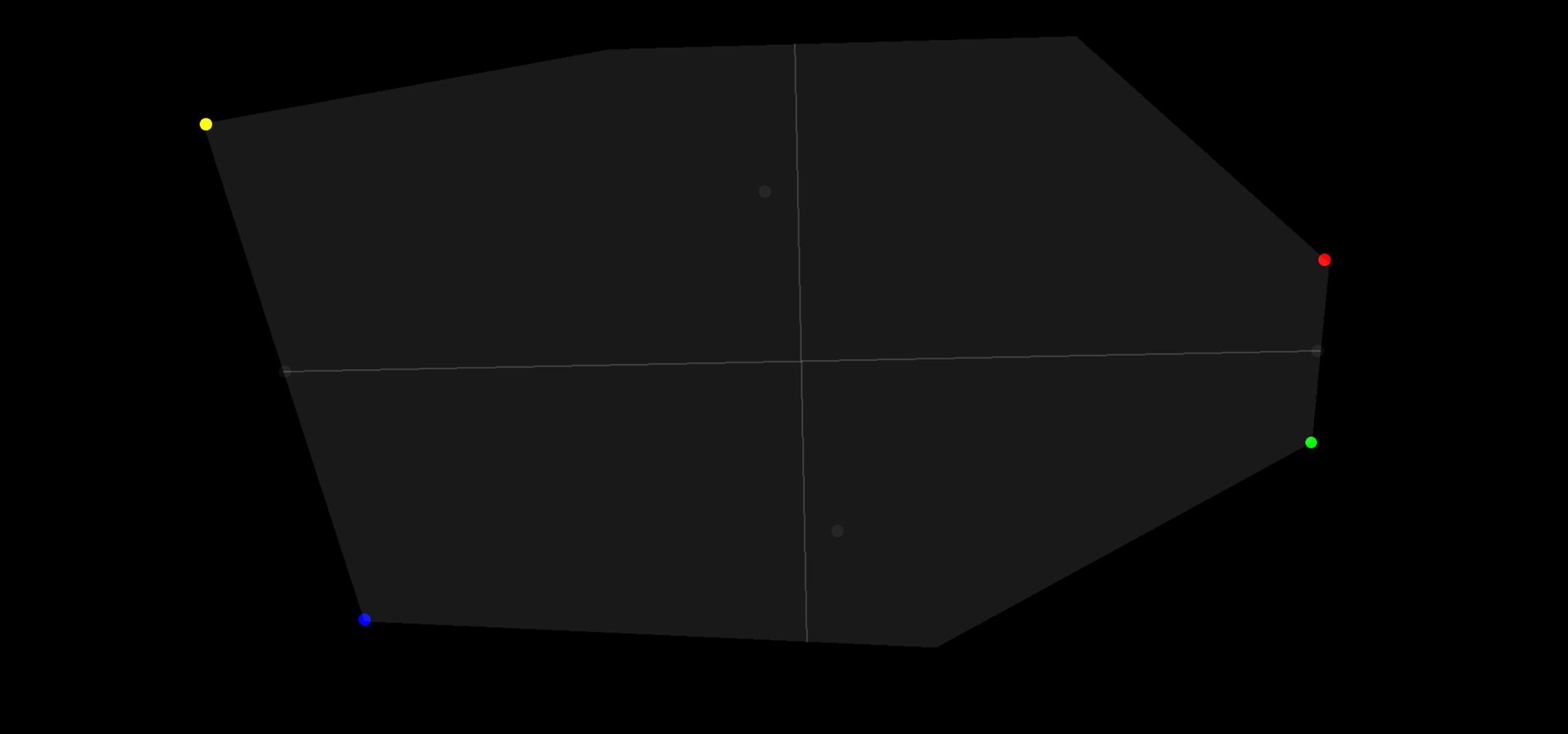
So now I have two maps which output uv position of the four corresponding points in R,G and B,A respectively.
There is a setup here that dilates these uv position through the shape by sampling the position at the center of each shape. However, I will gloss over this since its not actually needed and not important for this blog. I added it before figuring out the counter clockwise issue! I left it in the source file though, should you be interested in taking a look.
With these four points, it is then possible to align an axis grid by taking the mid points between 2 of them. I ended up exposing a variety of different alignment modes, which essentially came down to picking which two points to align an axis too.

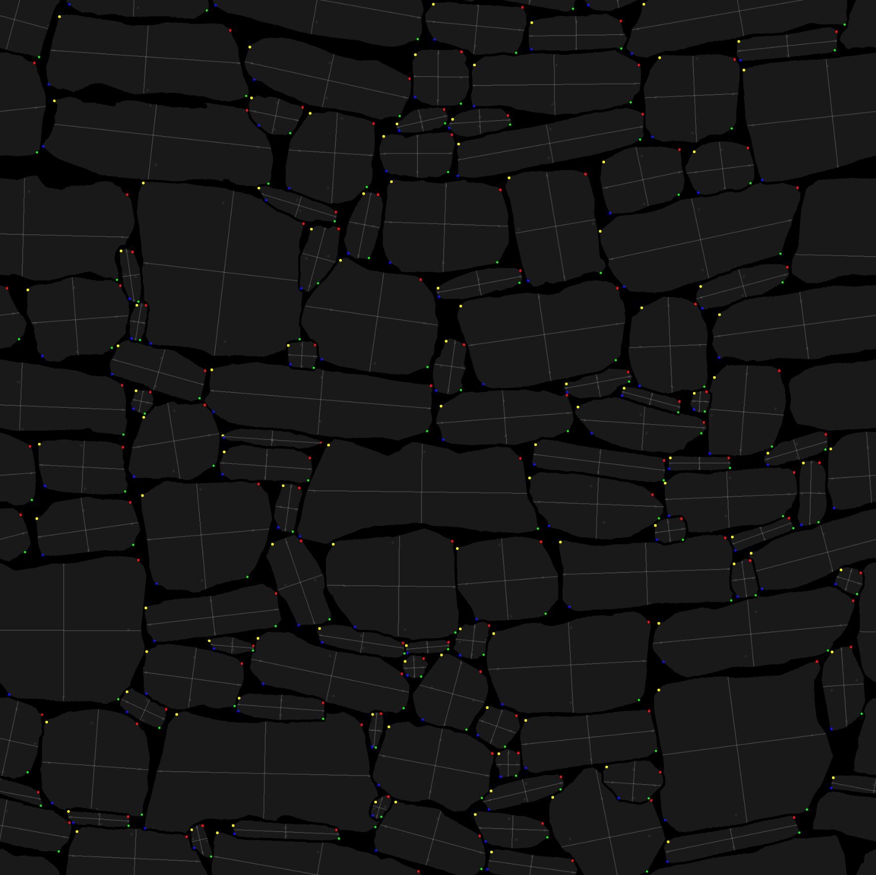
And here is an image showing the alignment points applied to a real example.
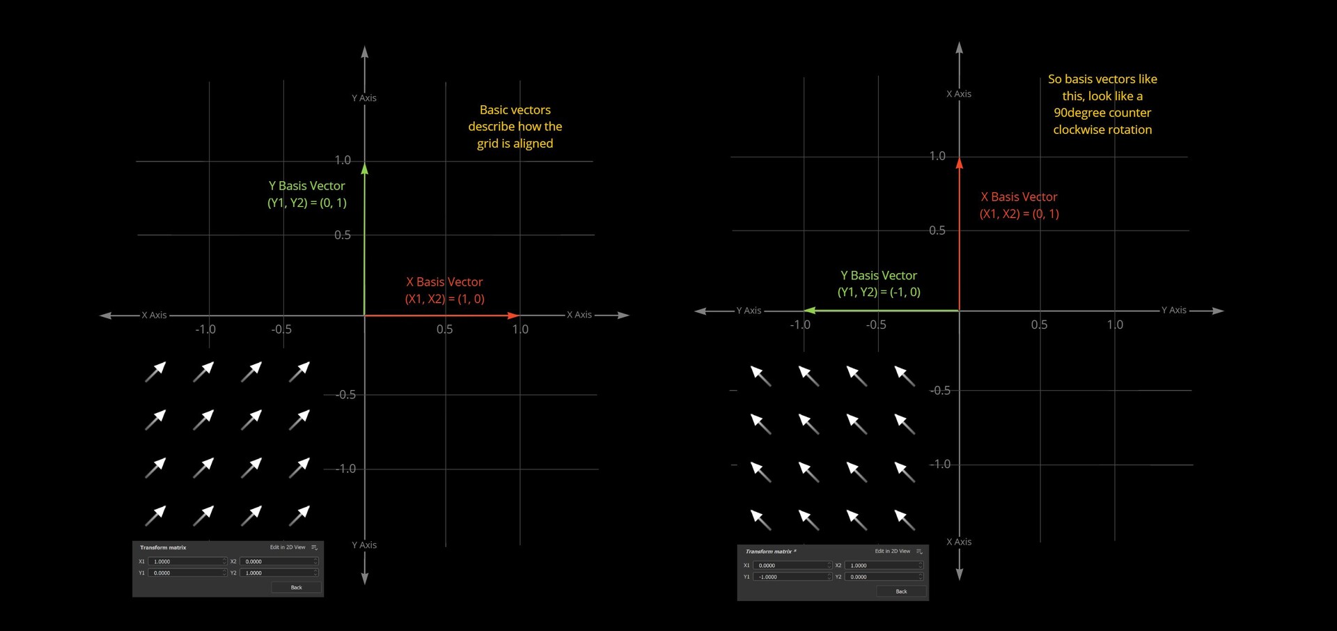
Now we have 2 points to form an alignment transformation matrix from, lets look at how that actually happens. For this we need to understand how transformation matrices work. More specifically, a 2D transformation matrix. The one you find on the transform 2d node.

In the transform 2d node, the values for X and Y correspond to the coordinates of two vectors which will define a grid. These are called basis vectors.
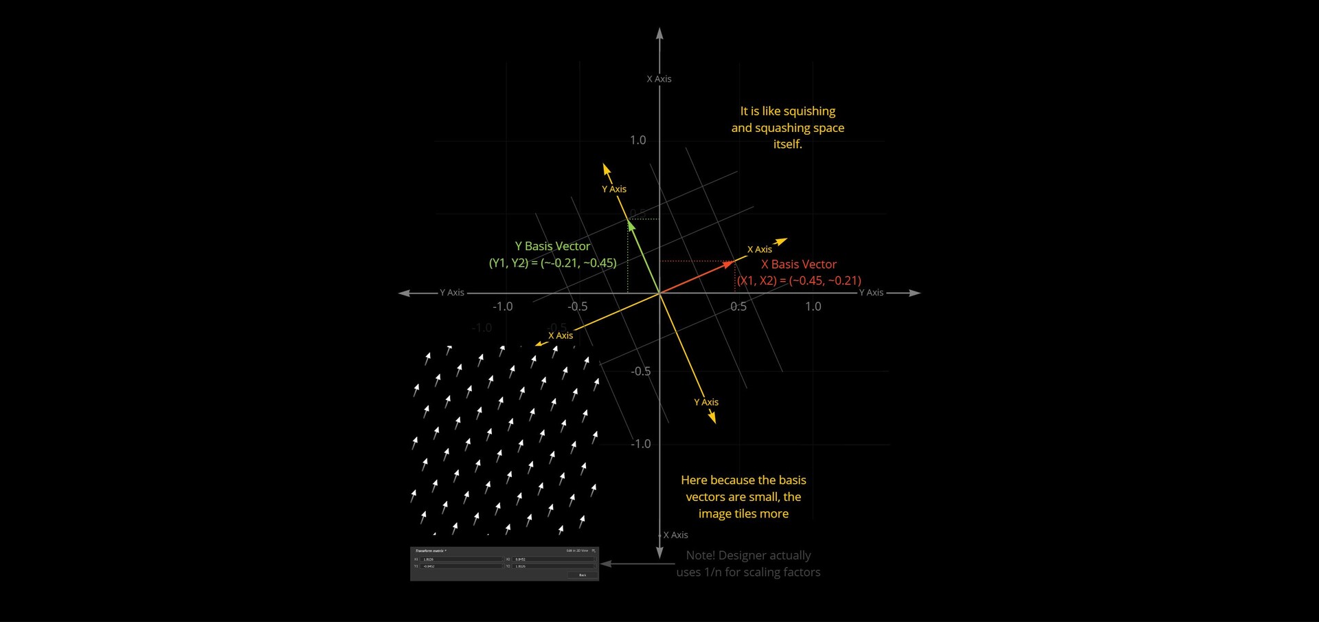
So, X1, X2 are the x, y components defining what the X basis vector should look like. Y1, Y2 the x, y components of the Y basis vector. These describe what the X and Y lines of a new grid should look like. You can think about it like rotating, squishing and squashing space itself into this new grid defined by these basis vectors.
Because we have two alignment points, we already have what we need to calculate at least one of the axis! We can use the delta between the two alignment points as an X basis vector.

But what about the Y axis? For that we can use a cross product. The cross product will give you the vector perpendicular to two input vectors in 3d space.

So, if we were to assume our texture is in 3d space, where the X axis is already known and the Z Axis looks directly towards the view, then the cross product between those two vectors would give us Y.
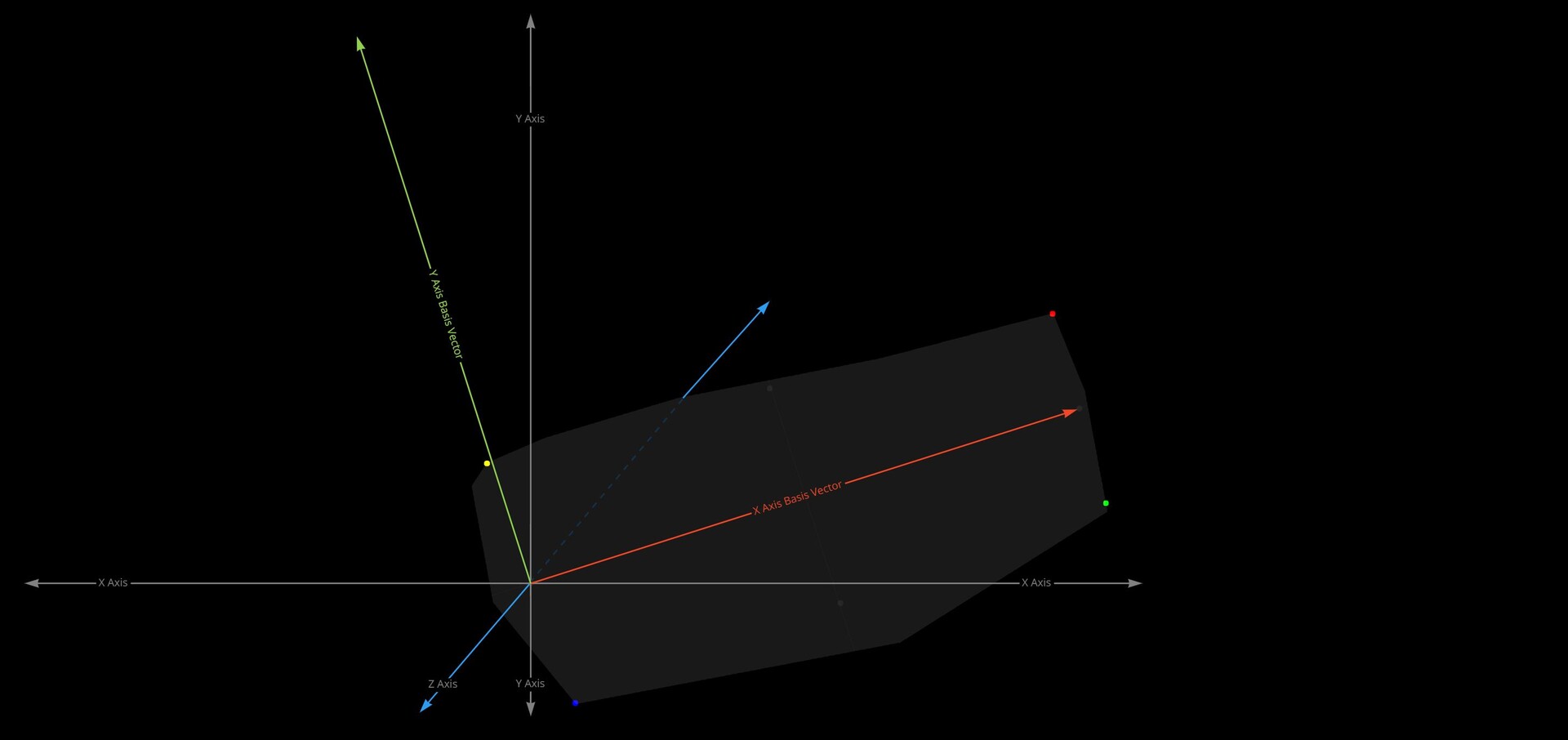
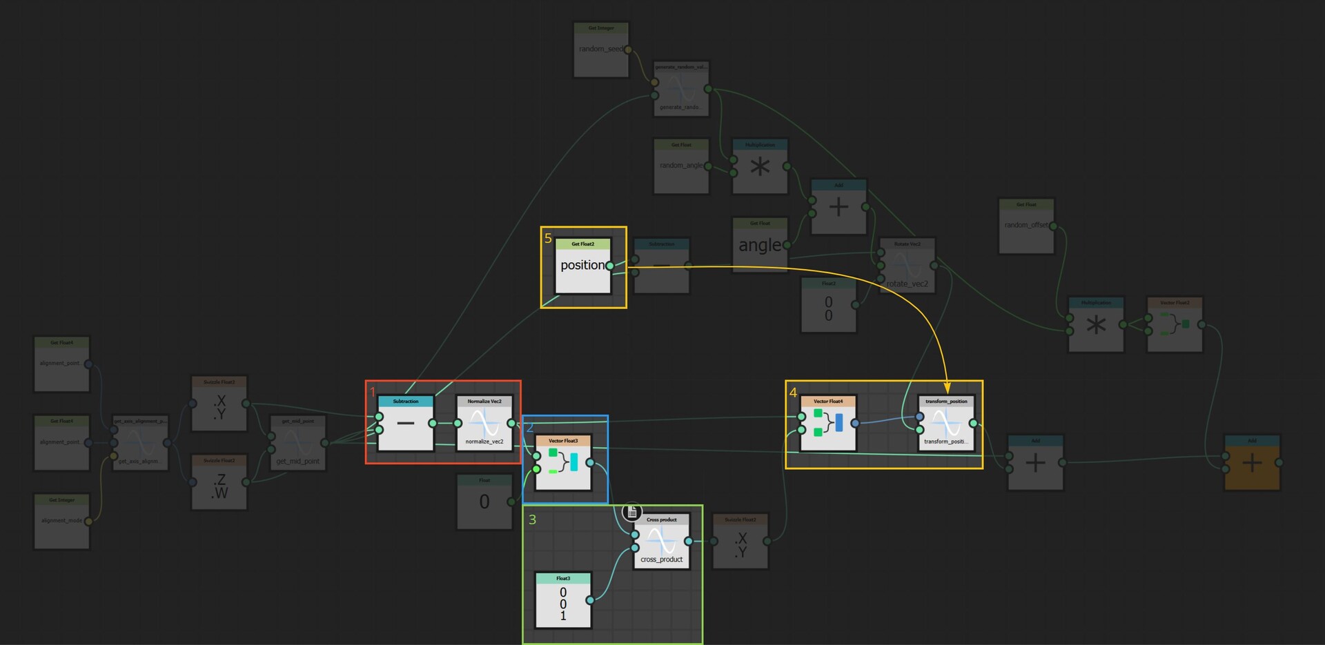
And here is the implementation for that. (1) We first construct the X axis and normalize it so the vectors length is 1. (2) Then convert that to a 3d vector by appending a z axis. We set the z component to 0 because we actually want this vector to rest on the texture plane. (3) Then cross product with a vector that points along the Z axis, which gives us the Y. (4) Since X and Y now both rest on the texture plane, we no longer need the z component, so that is removed and both vectors stored as the basis vectors of a 4x4 matrix. (5) Finally, the uv positions are multiplied by this matrix to perform the actual alignment.
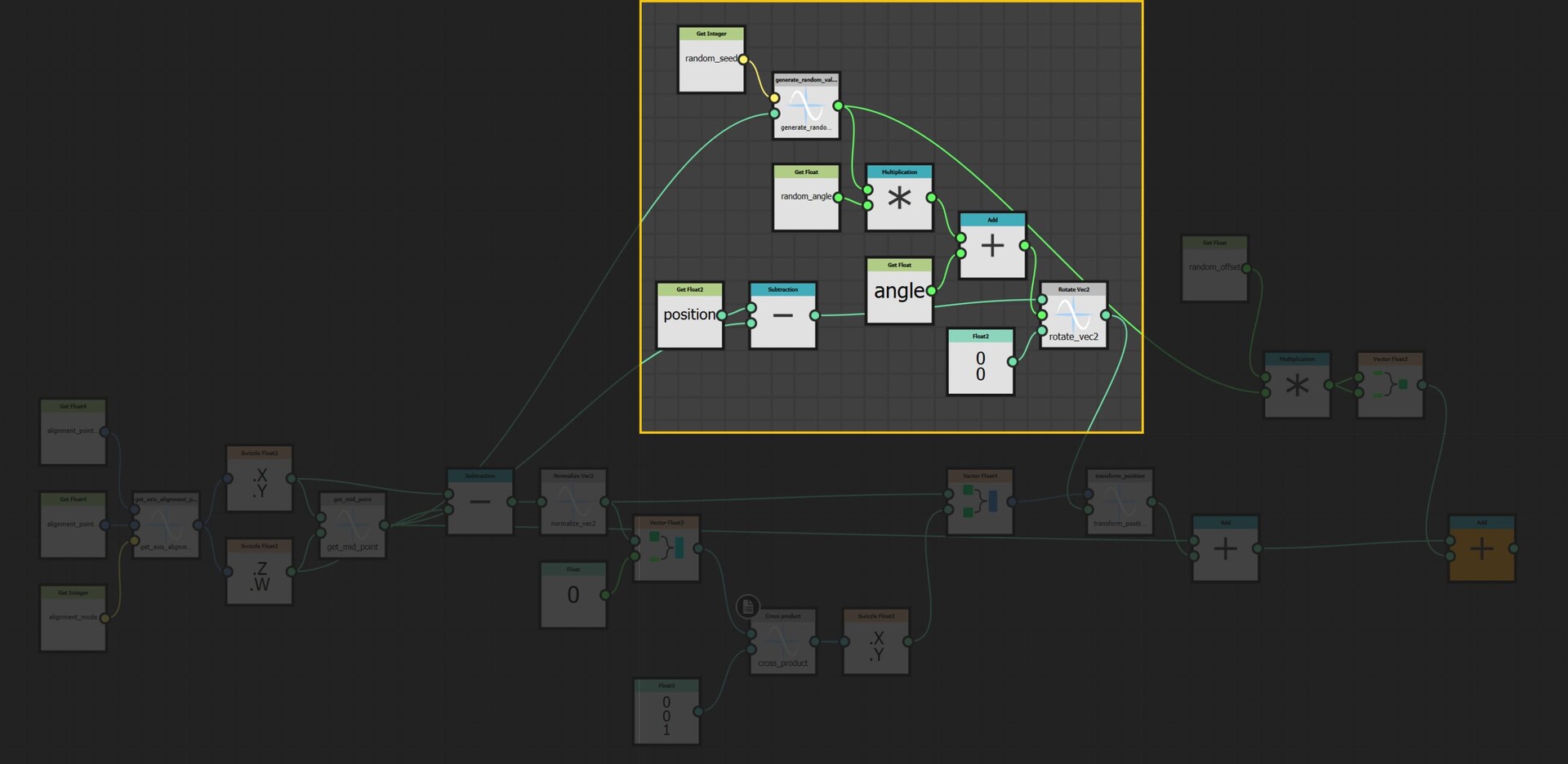
Also to note, there is a whole section here dealing with rotating the uv coordinates before being aligned and this was to provide some angle parameters to the user. I will leave you to explore that on your own too =)
However, as a small gotcha, if you are trying to implement this yourself; While Designer does come with a transform position node, it makes some assumptions about your uvs, so I needed to reimplement my own version to do the matrix multiplication.
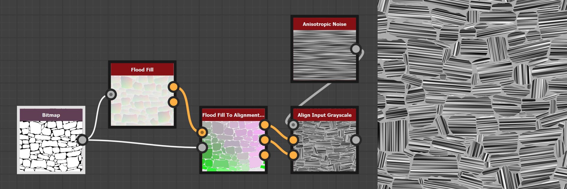
And that was the last piece of the puzzle. When we input an image, it will align the uvs to each shape. Here is an image showing an example.
So this concludes everything I wanted to discuss about the node implementation, but before we close out I did want to briefly talk about why all this doesn't really work!
Firstly, there is the limitation of convex shapes. We alluded to this before; the fact I am using the bounding box center to determine the distance means some shapes will fail to find a valid point.
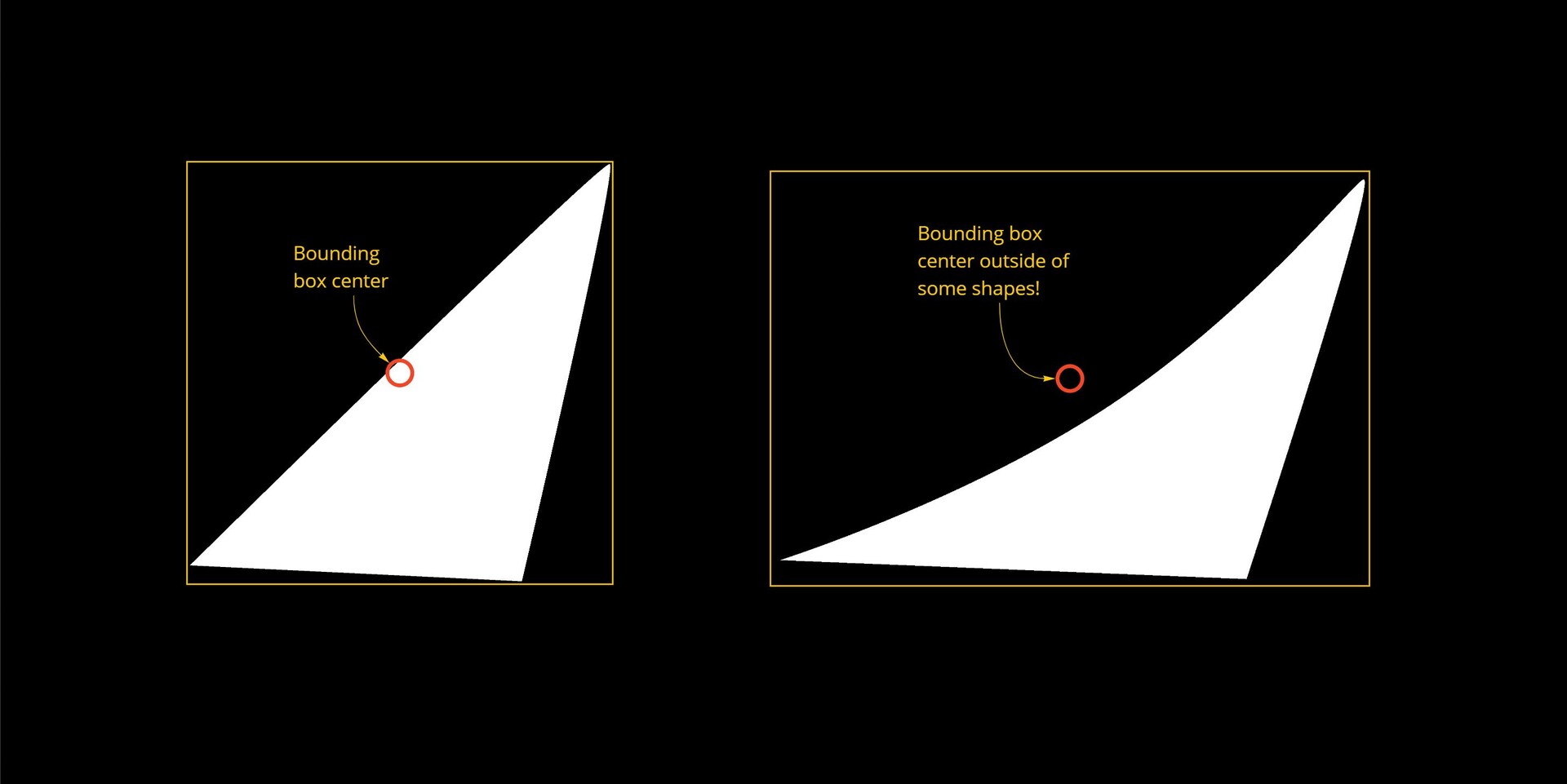
While this might not be a deal breaker (after all the use case is for convex stones), it does mean the setup is not 100% robust.
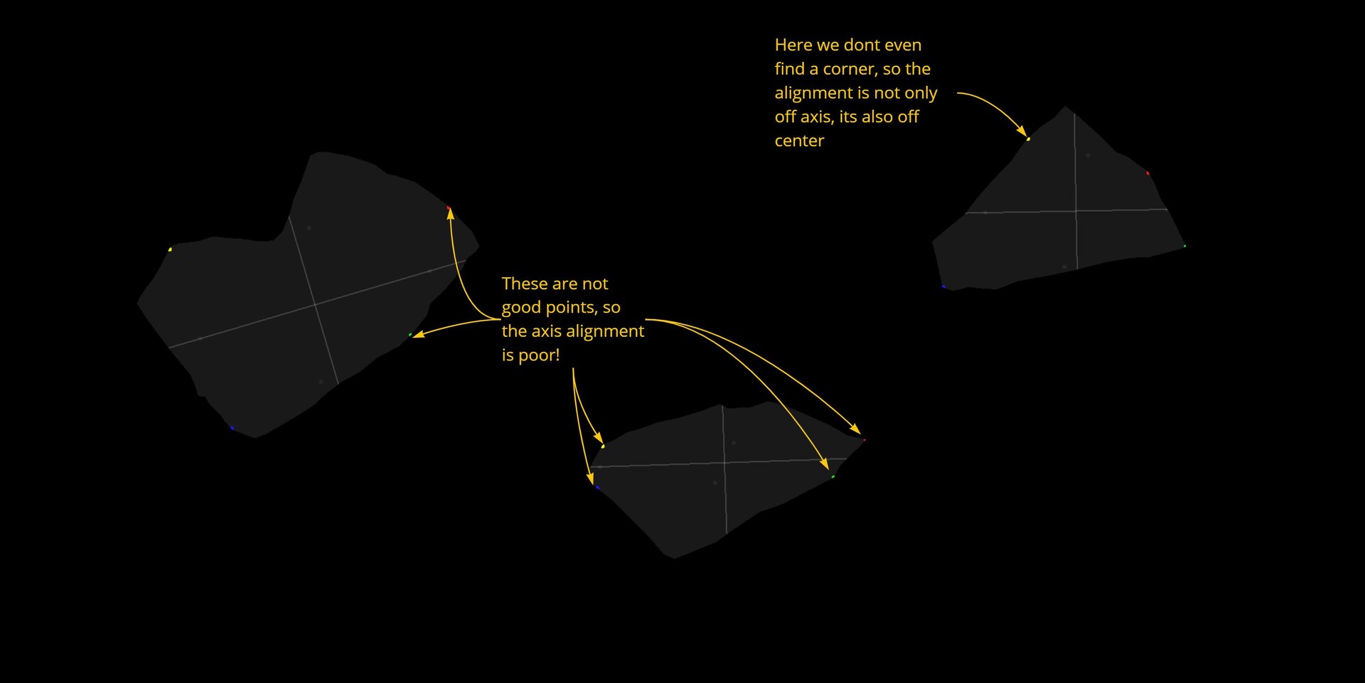
The biggest and main problem however is simple, this method is unable to find appropriate alignment points for a lot of shapes. This stems from the bad assumption that corners are going to be in the 45 degree directions (or which ever you pick) and the farthest point might not necessarily be in a good corner either. The node is particularly sensitive to shapes that are on the 45 degree angles.
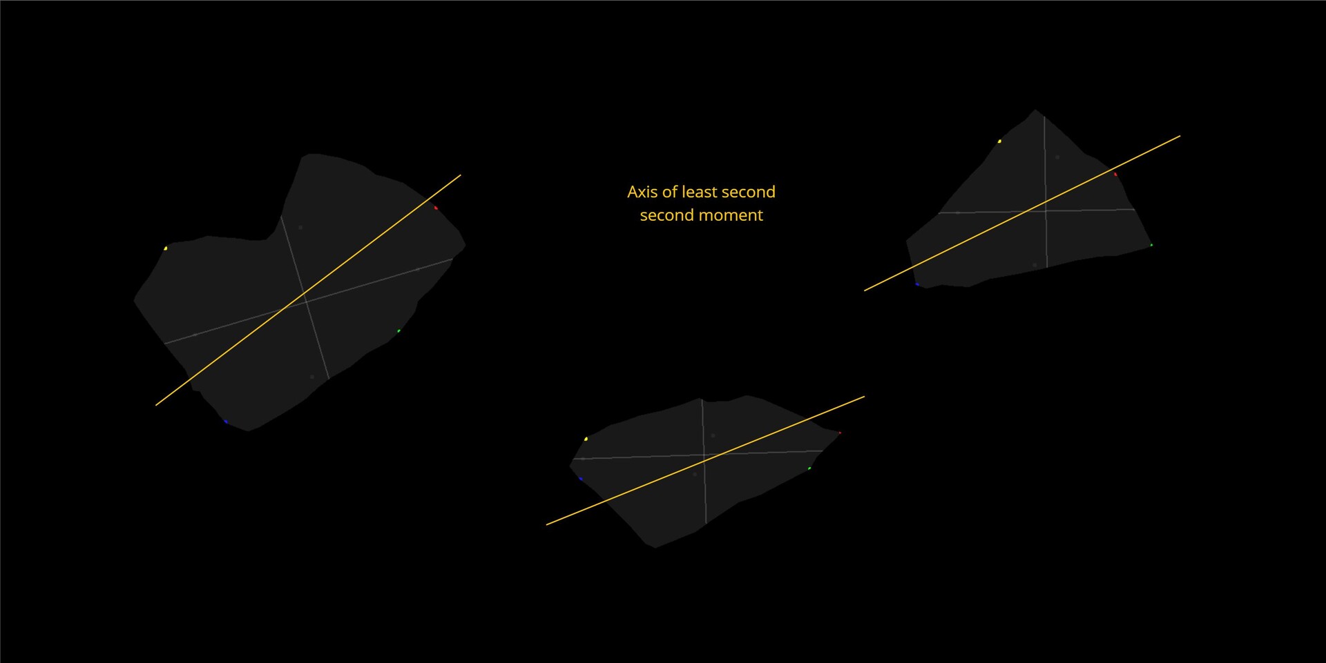
In the field of computer vision, there is an image processing concept called image moments and this is used to calculate things like weight, centroid and shape orientation. The second order moment specifically is used to find the orientation and can be thought of as finding the axis of minimum energy required to spin the shape. This I think would be a much more robust way of approaching the problem!
I recommend watching this wonderful lecture on the topic here https://youtu.be/ZPQiKXqHYrM
For now though, I am done with this problem and may pick it up again in the future. I will be putting the source files on my store (free) should you want to dig into the node further, Even though this didn't pan out as I wanted, I do hope it was interesting to you none the less.
Before closing out, I would like to specifically thank Igor Elovikov https://www.artstation.com/elovikov who was the one who really reverse engineered the flood fill node and was kind enough to share his findings with me. I definitely wouldn't have figured it out on my own! And of course Stan Brown https://www.artstation.com/stanbrown who is the one who got me hooked onto the topic and letting me use his textures for testing!
If you would like to take a look at the source files, they are available on my store https://www.artstation.com/a/14364831
Thanks for reading!