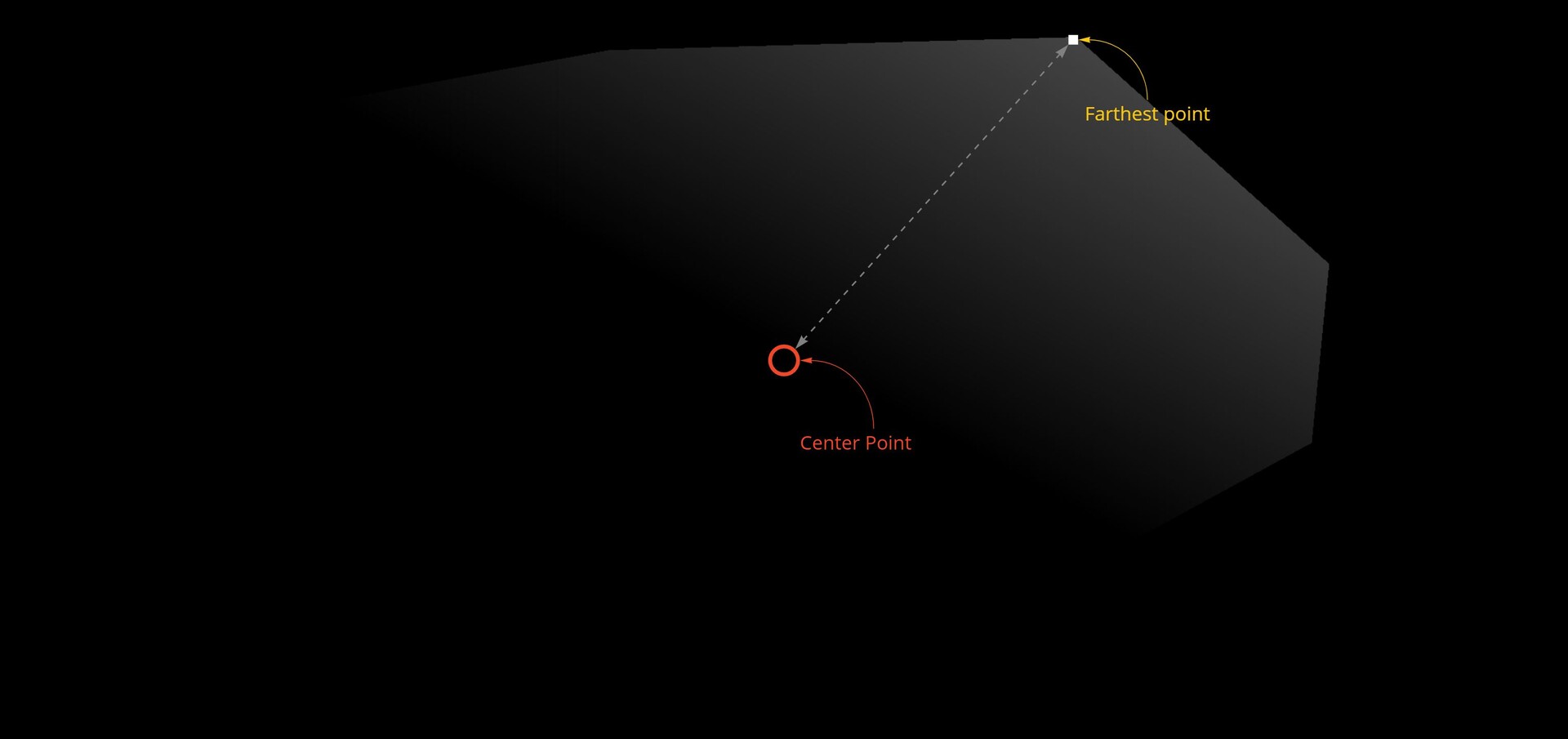
So where were we? To give a little recap, we needed to calculate the distance from the center to any pixel so that as we are stepping around the shape edges, we can use that value to find an appropriate corner point.
The issue right now is we can only deduce the farthest point, not the farthest point in a particular direction. We need a way to calculate that too.
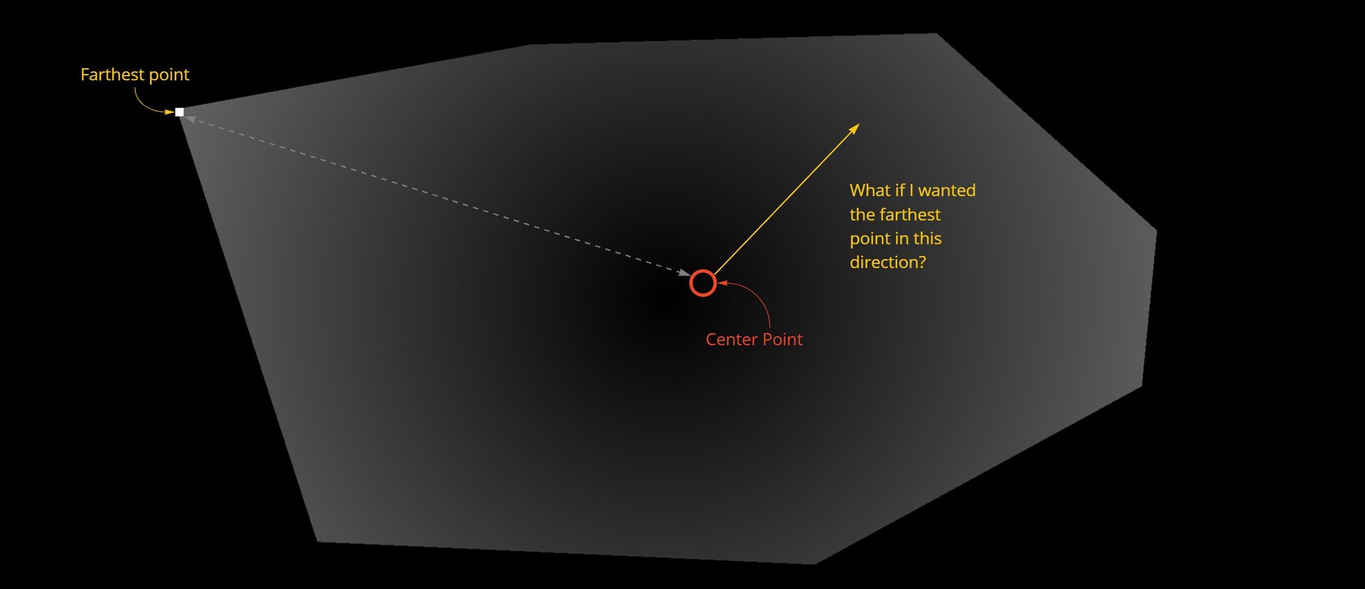
My idea to solve this was to calculate a direction map and then compare a desired direction against that texture. This could then be used to modify the distance map.
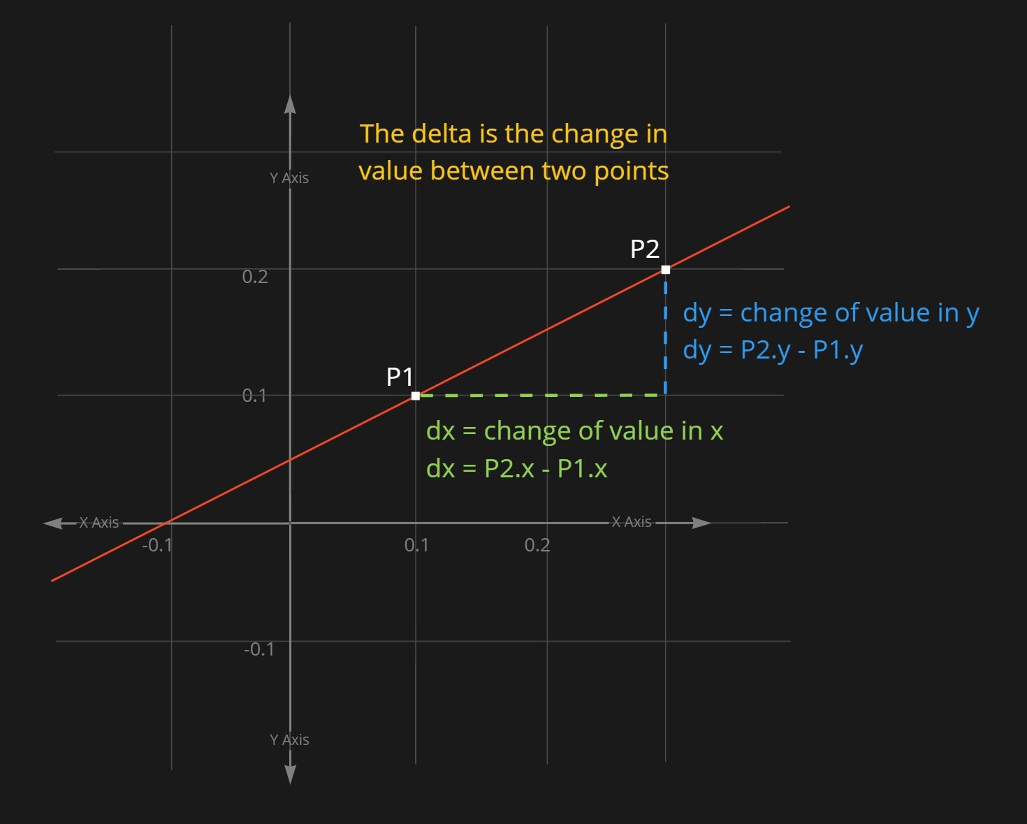
Lets look at how that works. It is possible to calculate the direction a gradient is sloping by finding the delta between neighbouring pixels. The delta is the name given to describe the change in a value between two points. So, if we plot a line on a graph. We could pick any two points on that line and say the delta in x (the change in x value) between those two points is the difference between the x value of point 2 and point 1. The same for Y axis.
So we could look at two pixels, in x and y respectively and use the values from the distance map to calculate the delta.
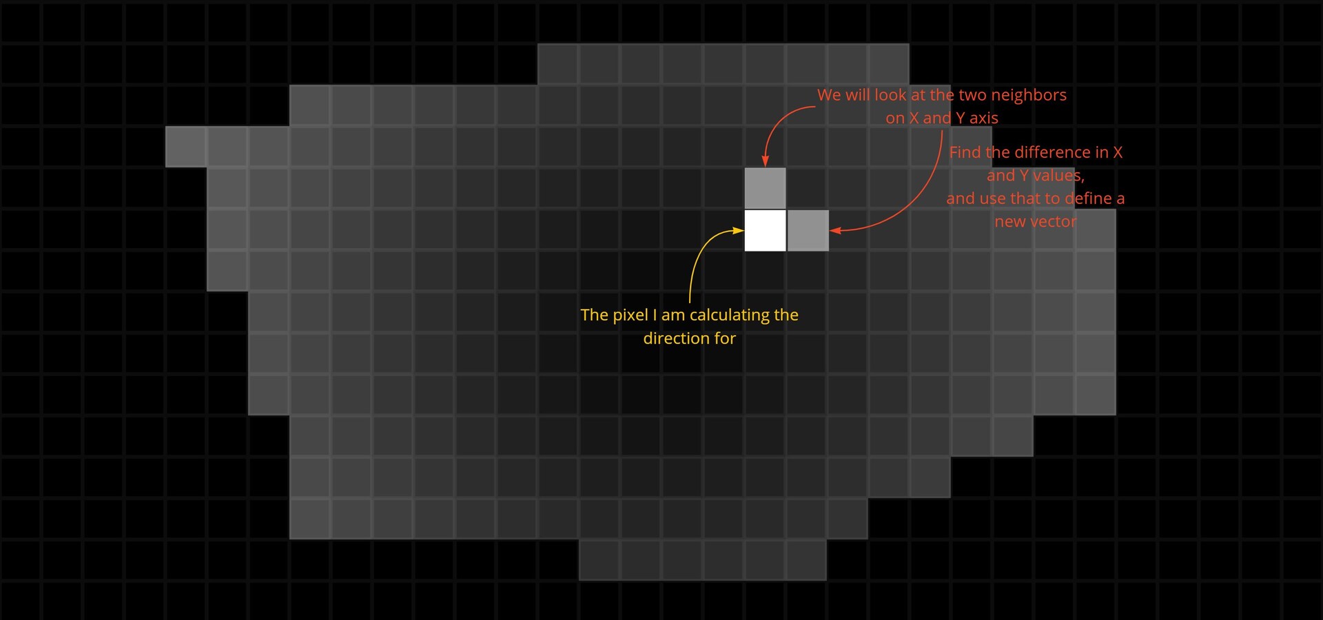
Which, if the then plot on a new graph, and draw a line from the origin to the point, it will give us the direction we need. The vector dx, dy is the direction the distance map is sloping.

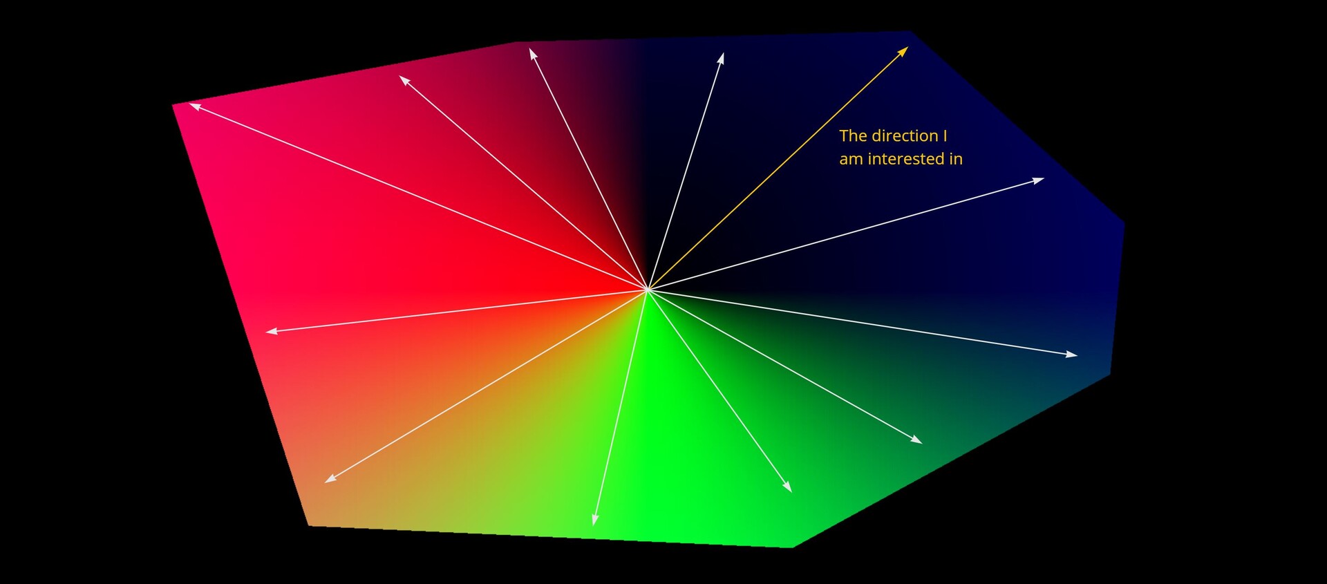
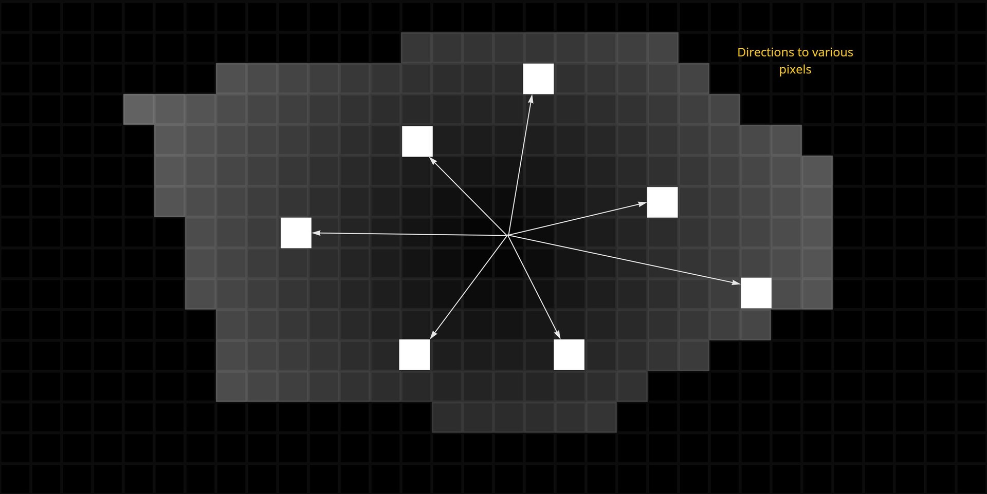
So doing this for all pixels, we would end up with a texture which describes the direction of the gradient at every point in the shape.
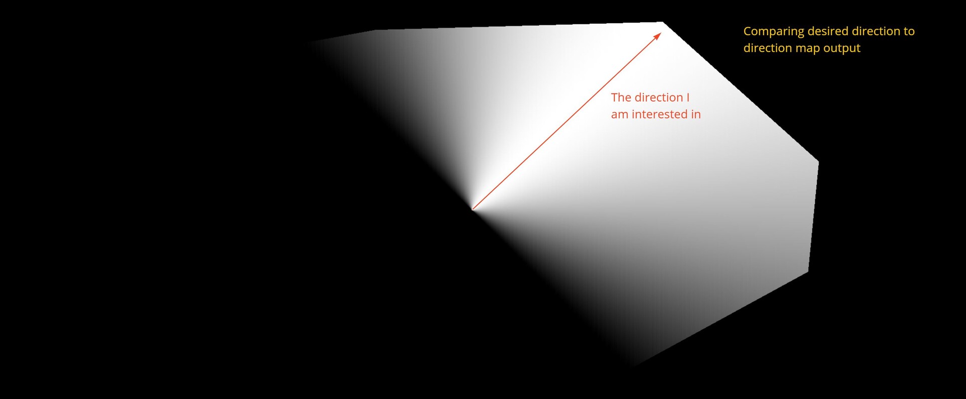
Then in order to compare the vectors with a chosen direction, we must normalize the result, so every vector now has a length of 1.
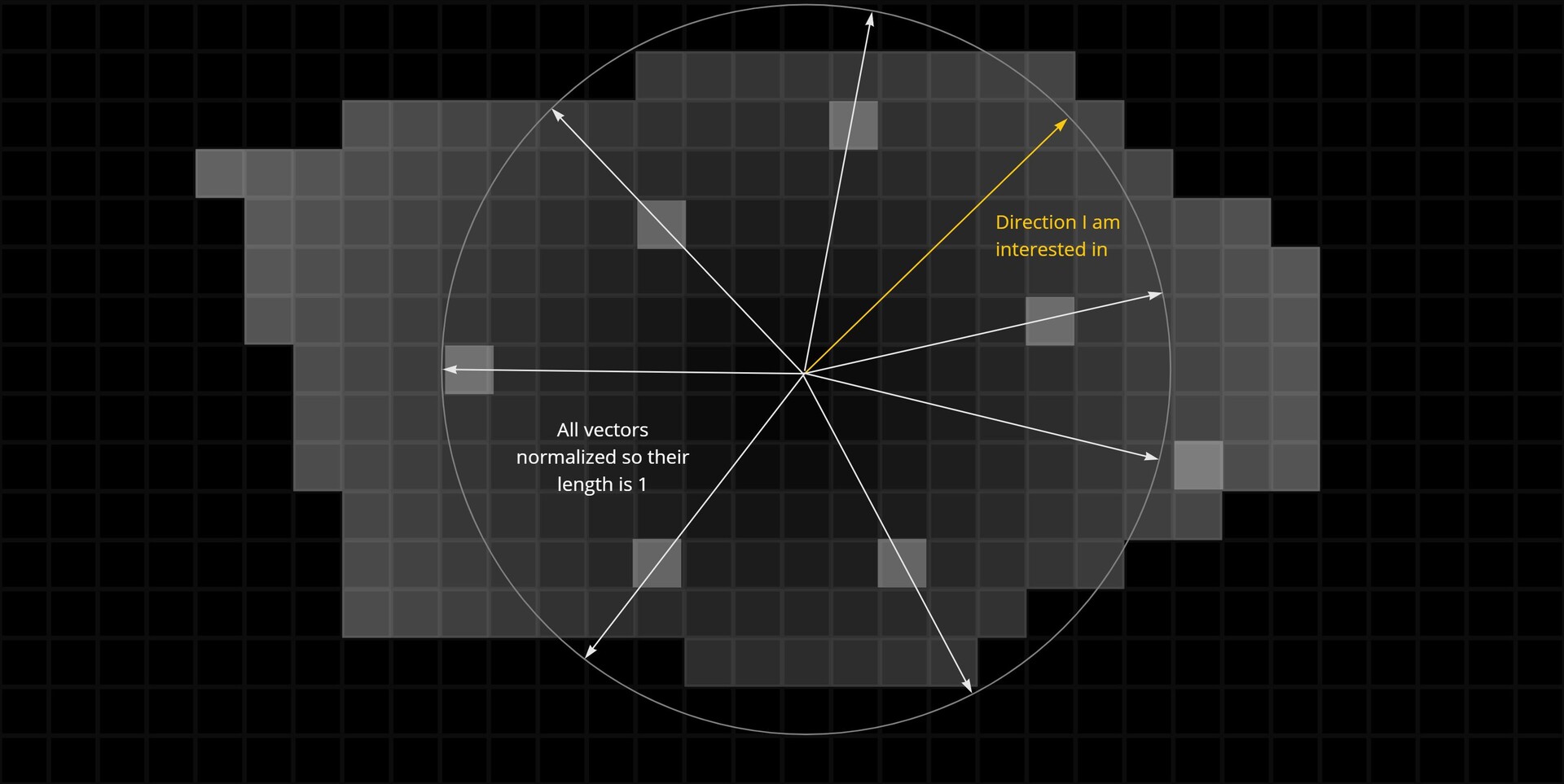
Taking the dot product is then comparing how close every direction is to the chosen one. Where the vectors are pointing in the same direction, the output is 1. As they become perpendicular, the output approachs 0 and where they point in the opposite direction, it approachs -1.

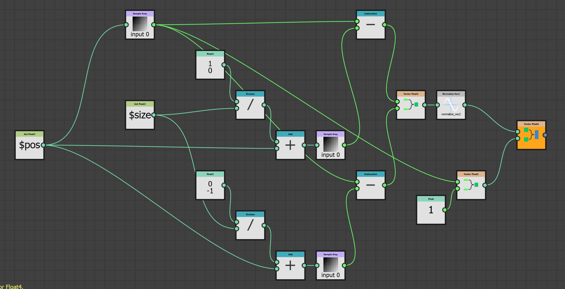
Here is the implementation for that. It is split across two pixel processor nodes.
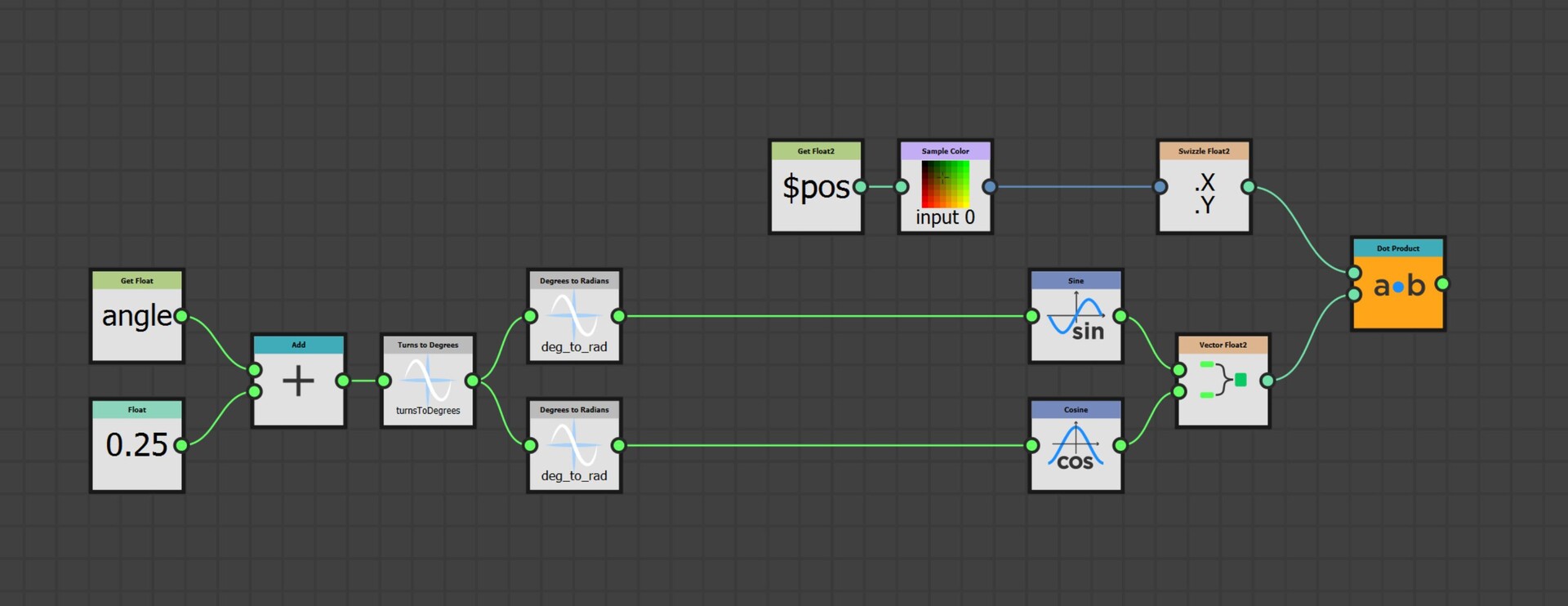
Now I can multiply my distance map by this directional map and use that to find the farthest point in the step function instead.
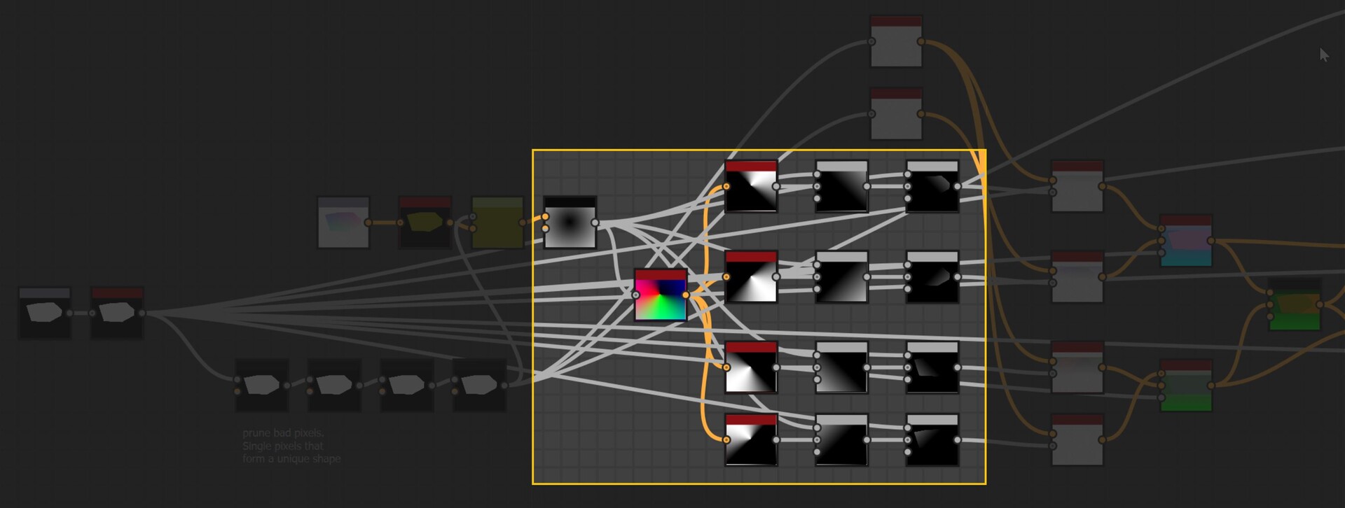
This is done four times in four directions.
Now lets look at the step function. We already saw how this works for the flood fill node in part 1, and this will be almost identical. We will store pointers to neighbouring pixels until finding an edge, then start spinning around it.
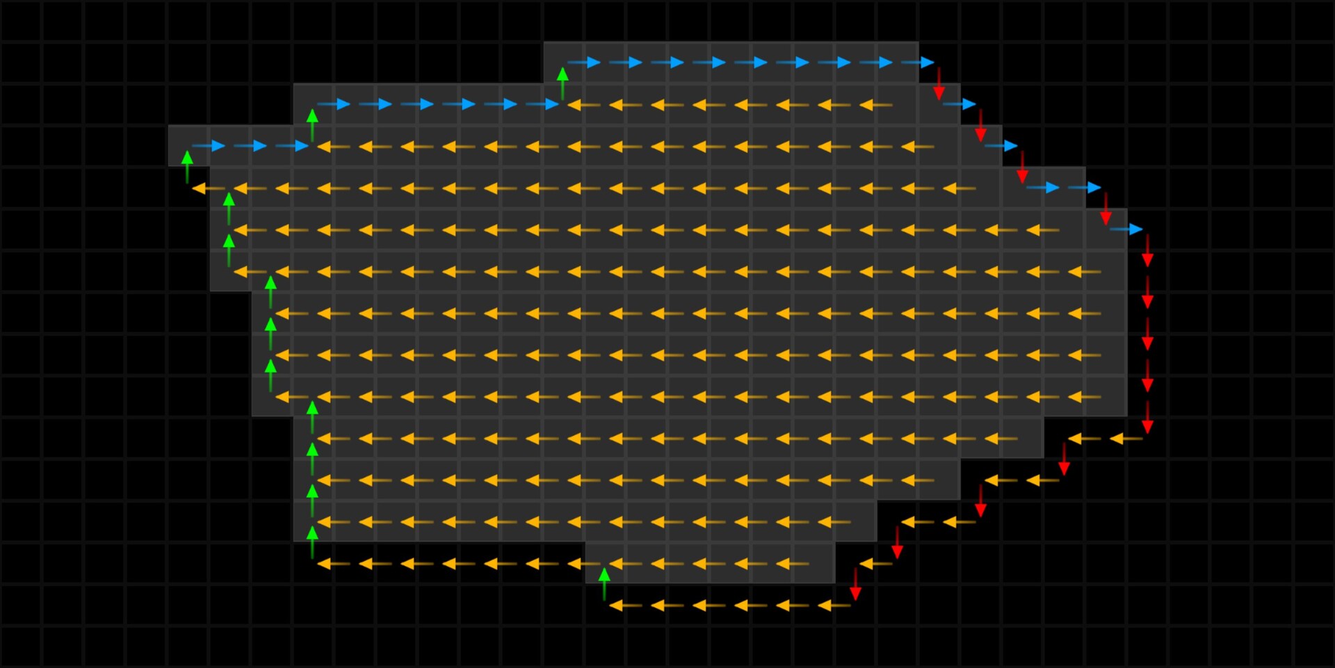
The only difference is, instead of storing the vector to a reference pixel, we will store the vector to the farthest pixel. This is as simple as storing the one with the largest distance value, taken from map we just calculated.

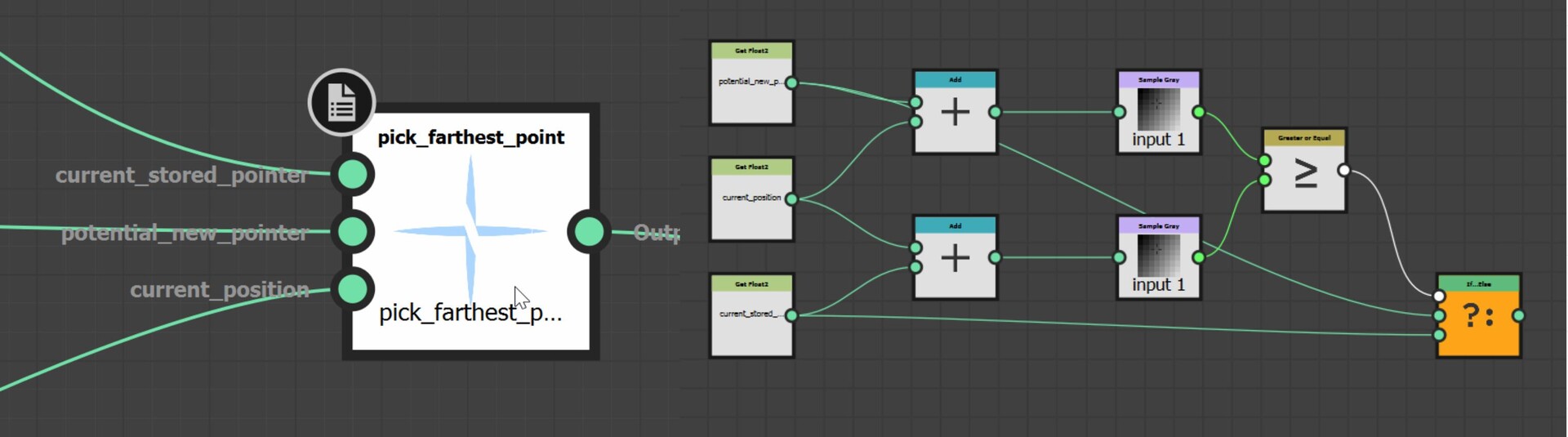
So, looking at an overview, we have some initial setup of values (the first pass in the step function), then successive jumps with each jump updating its pointer to a new farthest pixel.
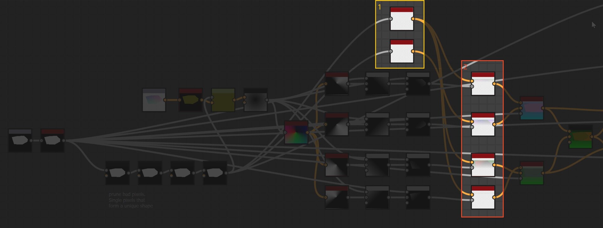
And here are the passes of successive jumps. In my testing I found 8 passes to be to little to resolve fully and 16 to be just fine. However, I added more steps just in case and setup some switches on blend nodes to toggle between if needed.

You may notice too that I have 2 nodes for the initial setup of values, with one going into 3 step functions and the other only into 1.

The reason for this was because in that particular direction, the values were not converging correctly on some shapes. Notice how on this shape there is a gap in the right hand corner.

To be honest, it is still unclear to me why this is happening, but I did notice it was only occurring when calculating the direction to the bottom right. This lead me to suspect it was something to with stepping around the edges in a clock wise pattern. So this second node is stepping counter clockwise instead. Indeed it fixes the issue, but if anyone has insight into why exactly we must step counter clockwise when calculating the bottom right direction, please let me know!
For now we will end part 3 and return in the next post to see what the step function outputs and how it was used.
https://www.artstation.com/blogs/benwilson/nZ67/alignment-node-development-part-4