Hi all, I am back with another blog series on a Substance Designer node I was recently working on.
It is designed to align an input image to flood fill shape orientations automatically and this series will be a deep dive into the workings of it.
This series will be a little different to the last one in that this node is actually a failure in many ways. Ultimately, I did not deliver on the goal I set out to reach but since I learnt a lot and think there is some interesting topics here, I wanted to do a series on it none the less.
While I do not recommend using the node, I have uploaded the source files to my store, so you can do so if you wish. https://www.artstation.com/a/14364831
We will start with setting up the problem, defining what exactly we are trying to solve. Then talk briefly about how I planned to approach the problem. After that we will dive into the flood fill node and discuss the algorithm and how its implemented. From here we can see how it relates to the implementation of this alignment node by looking at the math and node setup for everything. Finally, we will close out by discussing where the node falls short and why, and propose a potential better solution.
I will be assuming you have read my previous blog or have some familiarity with the pixel processor node for this, so make sure to skim through that if you haven't already! https://www.artstation.com/blogs/benwilson/PlRE/flood-fill-to-corners-development-part-1
SETUP THE PROBLEM
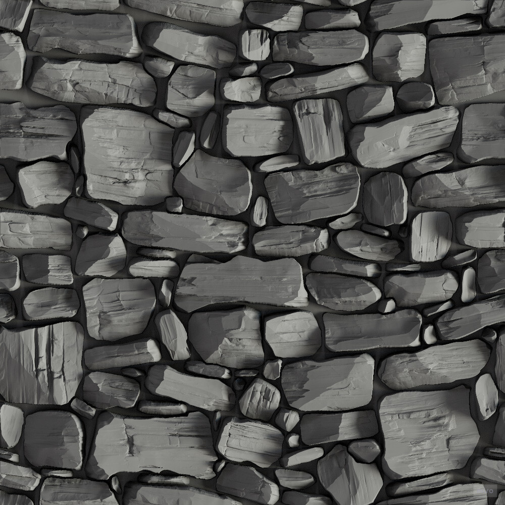
Let us begin with describing what problem I was trying to solve. I wanted to solve automatically rotating textures to individual stone shape orientations, given its input mask.
The use case I had in mind was texturing organic stone walls with very directional material information.
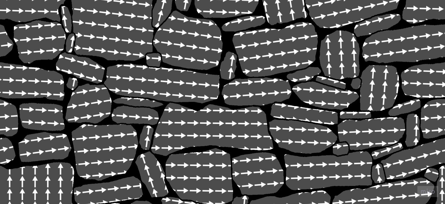
The general idea I took, and the one we will go through in this series, was to find corner points in the shapes and use those to align the uvs.

As I mentioned before, I do not think this is necessarily the best approach, but we will talk more about that at the end of the series.
FLOOD FILL NODE
The best place to start is with understanding how the flood fill node works. Firstly because it really underpins the whole approach I took, but also because it's just interesting.
Flood fill works in a very similar way to a jump flood algorithm. If you are unfamiliar with it, I highly recommend reading up a little. This blog by Ryan Kaplan is great https://www.rykap.com/graphics/skew/2016/02/25/voronoi-diagrams/
I also mention it in my last blog post about the corner node, where I unintentionally implemented a crude version of it. https://www.artstation.com/blogs/benwilson/2WpV/flood-fill-to-corners-development-part-3
There are two key points which are relevant to understand about the jump flood algorithm.
- You can query and store any data, not just distance to center. If you can define your query fully, you can flood it through a texture.
- There is no reason step increments must be in a grid pattern. You can step in any direction or shape you want, and we will see this later.
If any of that didn't make sense to you, then it's ok. Hopefully the visualisations going forward will make everything clearer.
If you are reading this, you are likely already familiar with what the flood fill node does. However, lets define it here on a more low level. The flood fill attempts to to find all edges of shapes in a binary image and calculate useful information like bounding box, uvs and how many shapes there are. It does this by finding a 'reference' pixel per shape, so it can guarantee that for every shape in the image, there exists only one corresponding pixel. This is how the flood fill to index node is able to count the number of shapes. And it does that by finding and spinning around the edges, gathering data about the shape as it goes.
This edge spinning is implemented as a series of increasing steps or jumps, which is the analogy to the jump flood algorithm. So lets look at that; the edge spinning is broken down into passes.

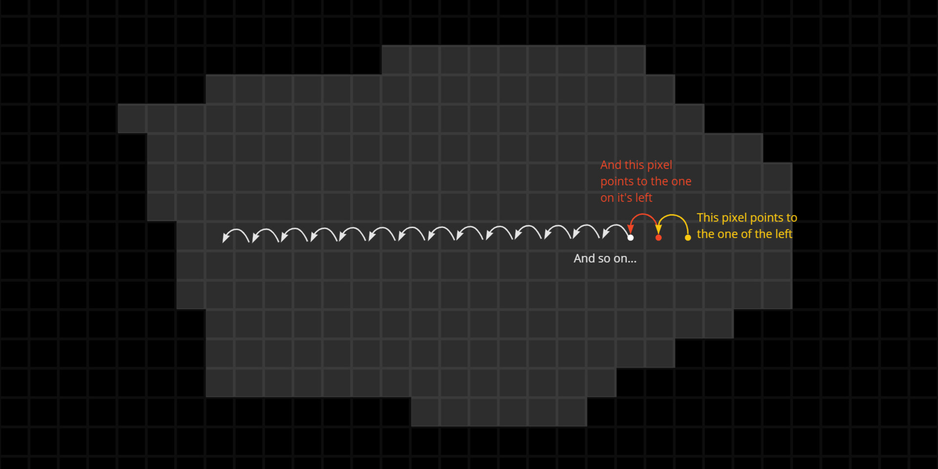
In the first pass, it will output a 'pointer' map. This is a texture where every pixel is pointing to its immediate neighbour to the left. When I say pointing too, I actually mean its storing the vector to that neighbour pixel from its current position in uv space. Or another way of saying it how many pixels do I need to move from where I am to reach that new pixel.
This vector is stored in the Red and Green channel.
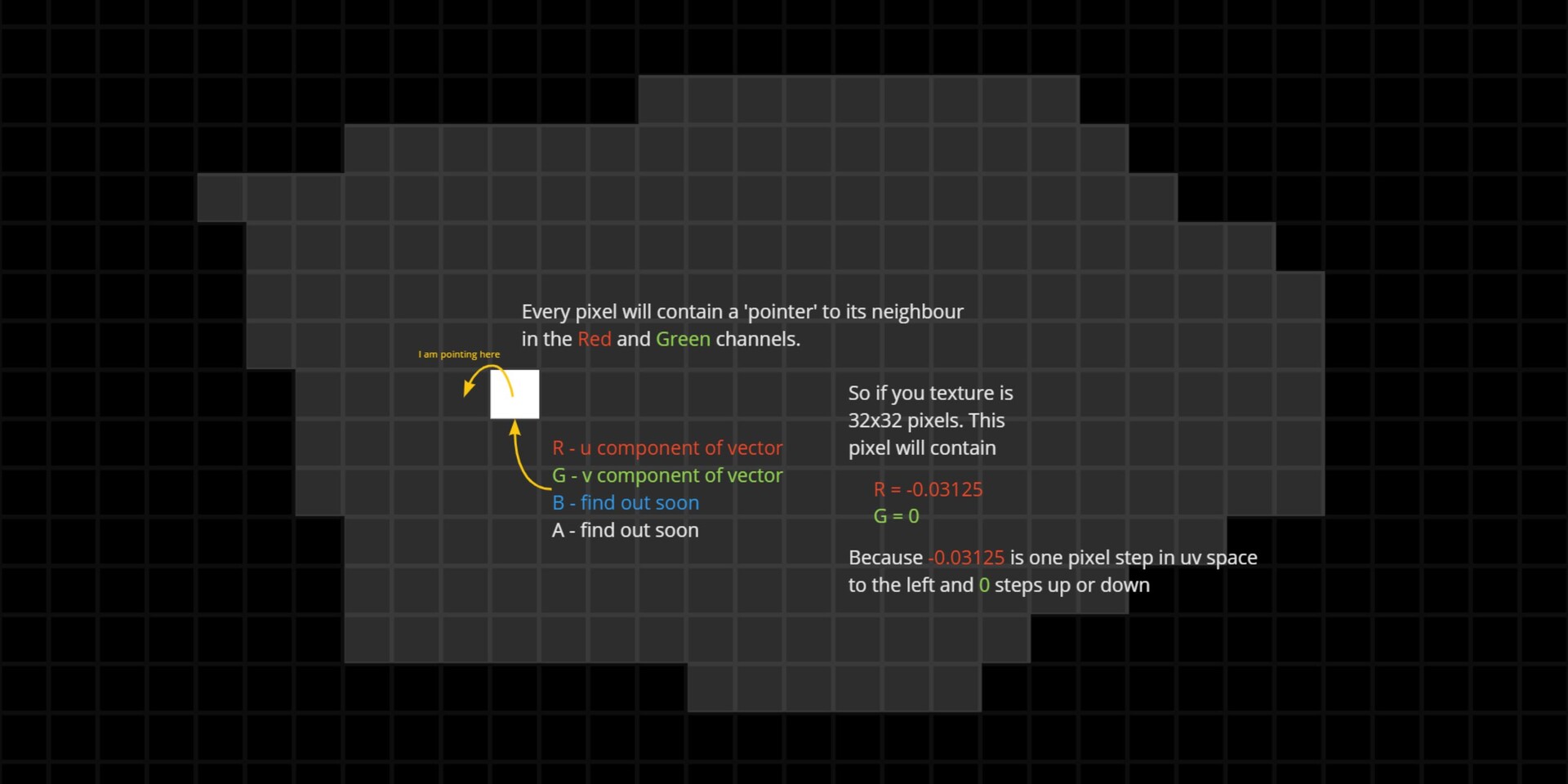
However, rather than blindly storing the left neighbour, there is some logic to determine if the pixel is on an edge. If it is, it will store the next clockwise pixel along that edge instead.

So after the first pass, we have a texture containing pointers at every pixel that looks something like this.

In the next step, it will look at the pointed pixel, find out where that one is pointing, then update itself with the same logic.
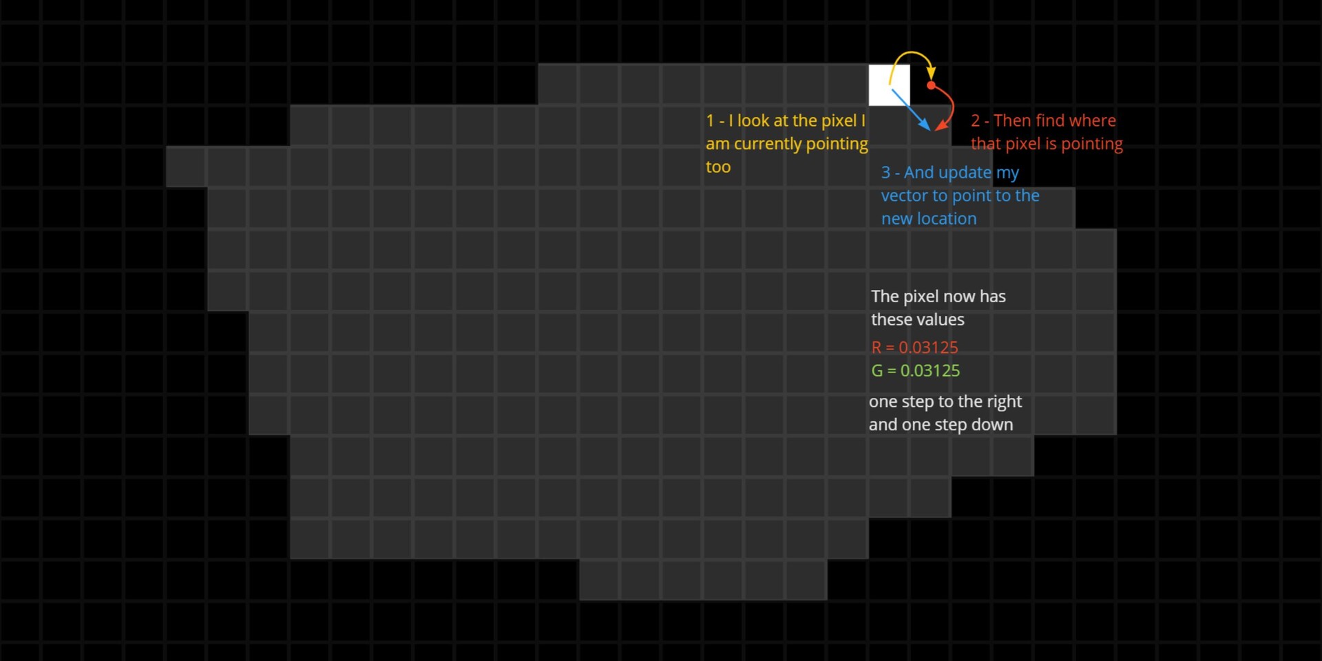
And this process repeats in all subsequent steps, each time making larger and larger jumps.
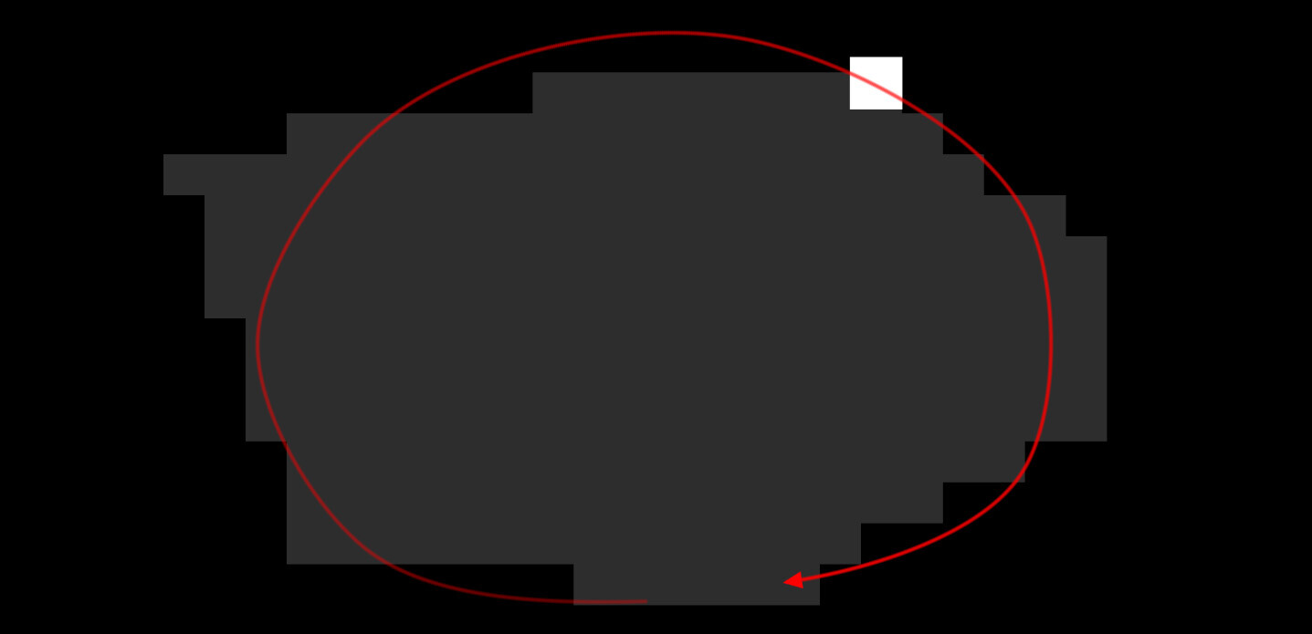
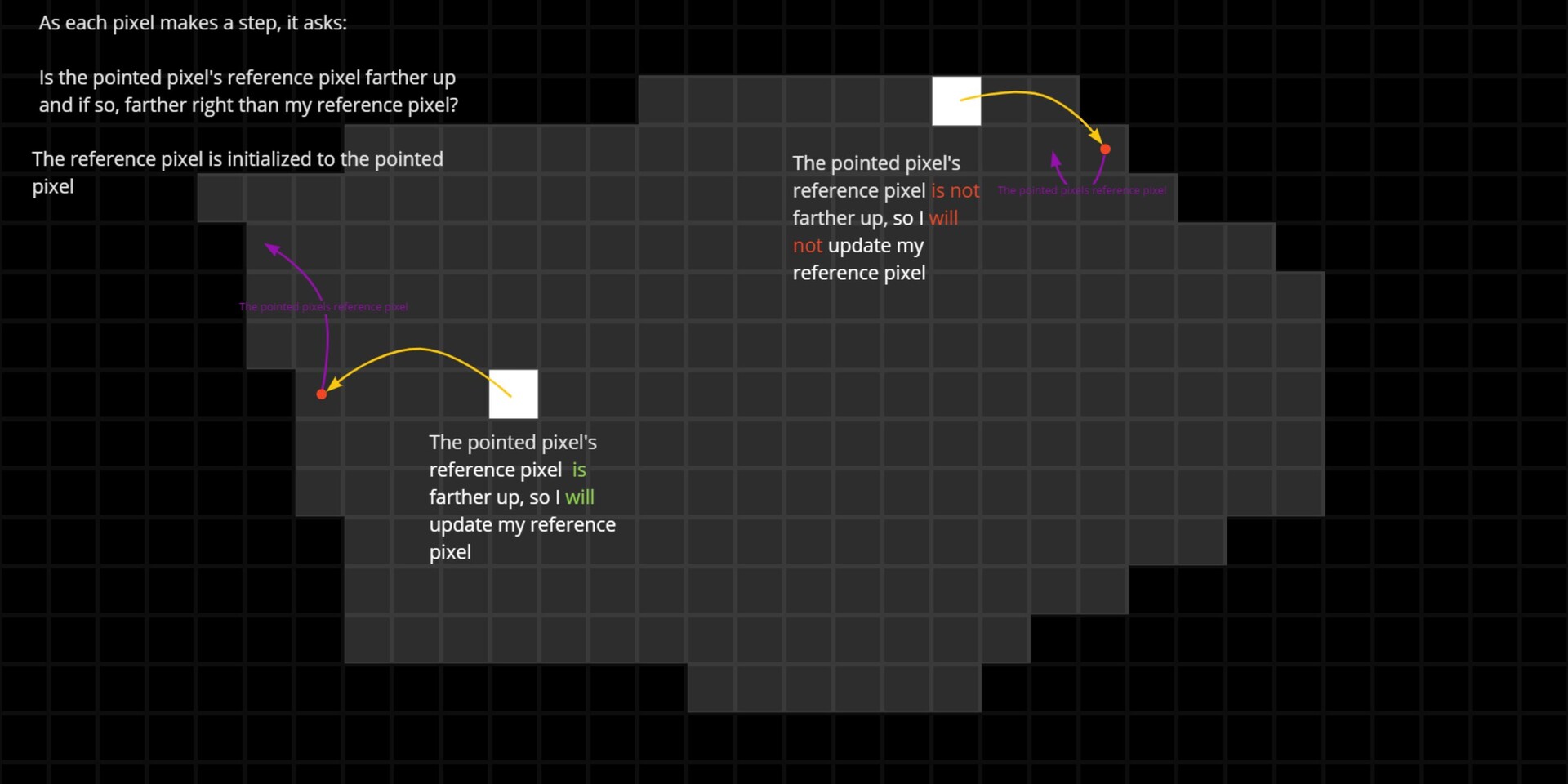
This is what gives rise to the spinning behaviour. Each pass makes incrementally larger jumps and when it finds an edge, it starts spinning around it. Now, as it makes each step, it also queries something about the pixels. In the case of finding a reference pixel, along with storing the pointed pixel, it also tracks the location of a reference pixel. At each step, it asks:
Is the pointed pixel's reference pixel farther up in Y and if so, farther right in X than my current reference pixel? If yes, it will update the reference pixel to this new one, otherwise it will keep it's current reference pixel. This reference pixel is stored in the Blue and Alpha components.
After enough passes, every pixel will have looked at another that was either updated directly or saw another pixel that saw another pixel who was updated. Quite the brain teaser, but essentially this is the same concept as jump flooding, except constrained to a shapes bounding edges. At the end of the passes, the comparison result 'spreads' through the shapes in the image. The net result of this is a texture where every pixel points to some reference pixel, the top right one in this case.
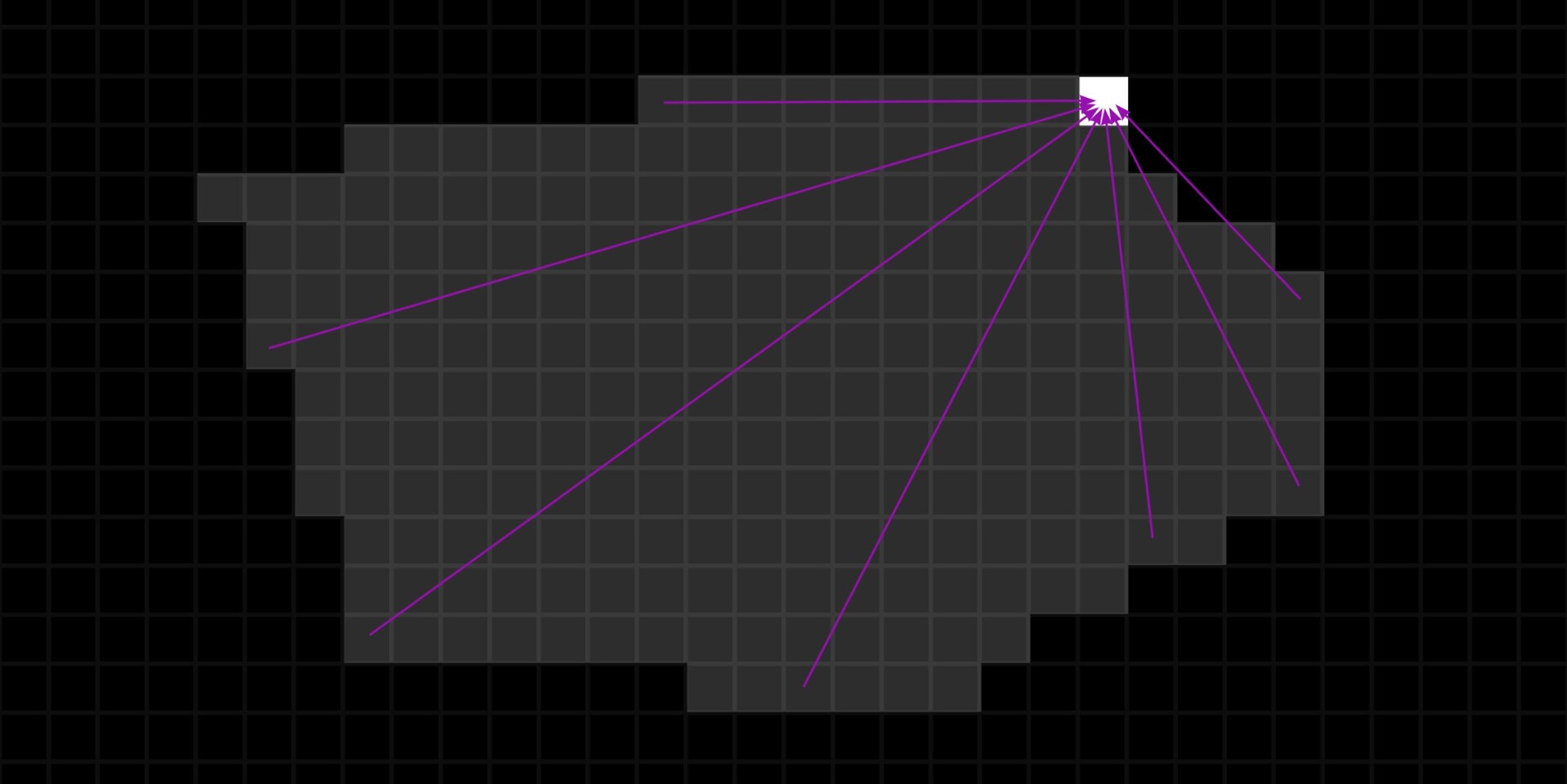
And to clarify, this vector is stored in the Blue and Alpha component. Red and Green will still be pointing to some arbitrary location on the edge after all the passes.
The flood fill node does a lot of other things too. It calculates bounding box information during these steps, it identifies inside and outside edges and there is a whole part of the network dedicated to solving shapes with holes. I am glossing over a lot of details too, some of which I have not fully understood myself, but what we just went through is the gist of it, and what you need to know to understand how this alignment node works.
In part 2 https://www.artstation.com/blogs/benwilson/AmVz/alignment-node-development-part-2, we will begin looking at the implementation for the alignment node itself.